Shunt calibration, Full-bridge configuration – MTS FlexTest Models 200 User Manual
Page 148
MTS FlexTest® Models 40/60/100/200 Controller Hardware
Digital Universal Conditioner Mezzanine Cards
Mezzanine Cards
148
Digital Universal Conditioner (DUC) Bridge Connections
The following figures show the full-, half-, and quarter-bridge configurations
for a DUC that is configured as a DC conditioner.
Shunt calibration
The shunt-calibration resistor (R Shunt) sockets are located on the front of
the I/O carrier board. Use system hardware-mapping software to specify
which leg of the bridge is shunted during calibration.
Note
If you use MTS TEDS modules or MTS transducers with integrated
shunt-calibration resistors, you must insert a jumper plug (MTS part
number 100-188-097) into the socket for each transducer input
where you will use the integrated shunt-calibration resistor.
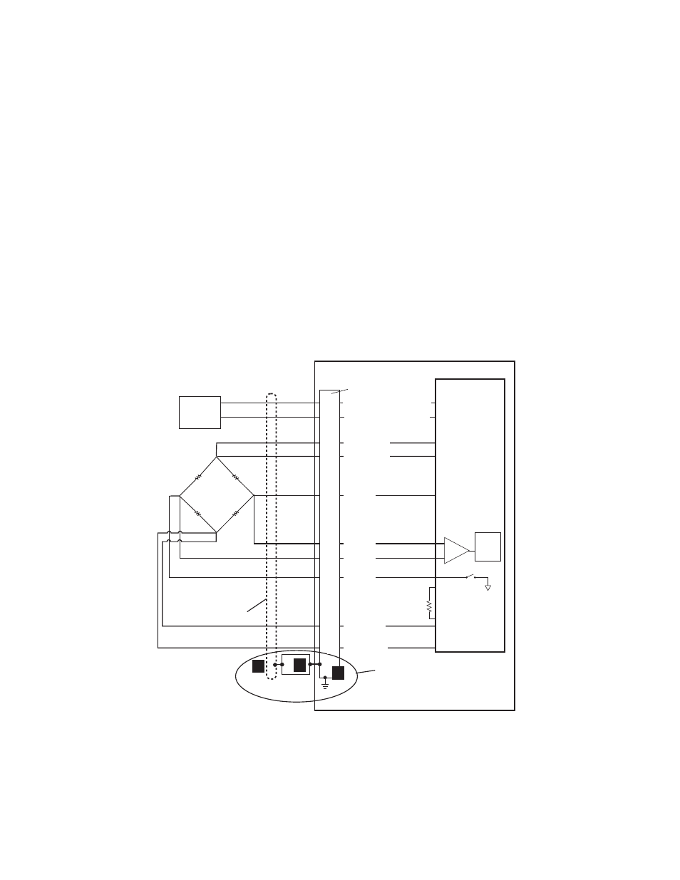
Full-bridge
configuration
The following figure shows a full-bridge configuration.
-
Ex
-Ex Sense
I/O Carrier Board
Front-Panel
RJ-50 Connector
Transducer
RJ-50
Cable
Plug
2
1
Cable
Shield
3
Cable Grounding
1 The cable shield connects to the metal
shielding on the RJ-50 cable plug.
2 The cable plug shielding connects to the
I/O carrier board body.
3 The I/O carrier board connects to earth
ground through the chassis.
DUC
A to D
SW1B
3
8
6
4
7
5
9
2
+FBR
R
Shunt
+Ex Sense
+Excitation
-Excitation
-Ex Sense
+FB
-FB
-FBR
IEEE
1451.4
Circuit
+ IEEE 1451.4 Class 2
10
1
- IEEE 1451.4 Class 2