Cable specification – MTS FlexTest Models 200 User Manual
Page 66
MTS FlexTest® Models 40/60/100/200 Controller Hardware
Model 494.41 Single-Station System Board
FlexTest Controller Configurations
66
UPS Connections for the Model 494.41 System Board (FT40)
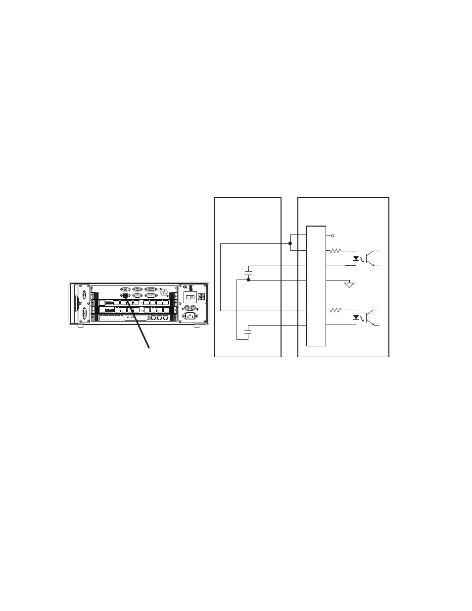
The following drawing shows UPS connections for the Model 494.41 System
board. Once connected, use your controller software to add the digital input
resources and configure the digital inputs to perform various actions in response
to the UPS signals.
Note
See your controller software user guide for information on how digital
inputs are assigned and used.
Cable specification
To maintain EMC compliance, the J54 Digital Input cable must comply with the
following specifications:
Connector type–9-pin contact, type D, male EMI connector.
Back shell–EMI metallized plastic or metal.
Cable—26 to 22 AWG, 4-conductor with an overall braided shield that is
connected to the backshell at the chassis.
494.41 System I/O Board
Power
100-240 VAC
50-60 Hz, 1-2 A
DA Output
J24
1 2 3 4 5 6 7 8
1 2 3 4 5 6 7 8
J54 Dig In
J49
Aux Pwr
J25 Hpu
Dig Out J55
Intlk J43
E-stop J29
J28 HSM
LAN 2
LAN 1
DEBUG
MOT
O
ROLA
10/100 BASE T 10/100 BASE T
SCSI
BUSY
PIB
BUSY
PCI MEZZANINE CARD
PCI MEZZANINE CARD
J54 Digital Input
+24 V DC
UPS
AC Fail Contacts
Open = Logic 0
1
2
3
8
4
5
J54
Dig In
Digital Input 1
Low Battery Contacts
Open = Logic 0
Digital Input 2