Device connections, Power connections, Output fuses – MTS FlexTest Models 200 User Manual
Page 226
MTS FlexTest® Models 40/60/100/200 Controller Hardware
Model 494.32 8-Channel DI/O Breakout Box
Digital I/O and Transition Boards
226
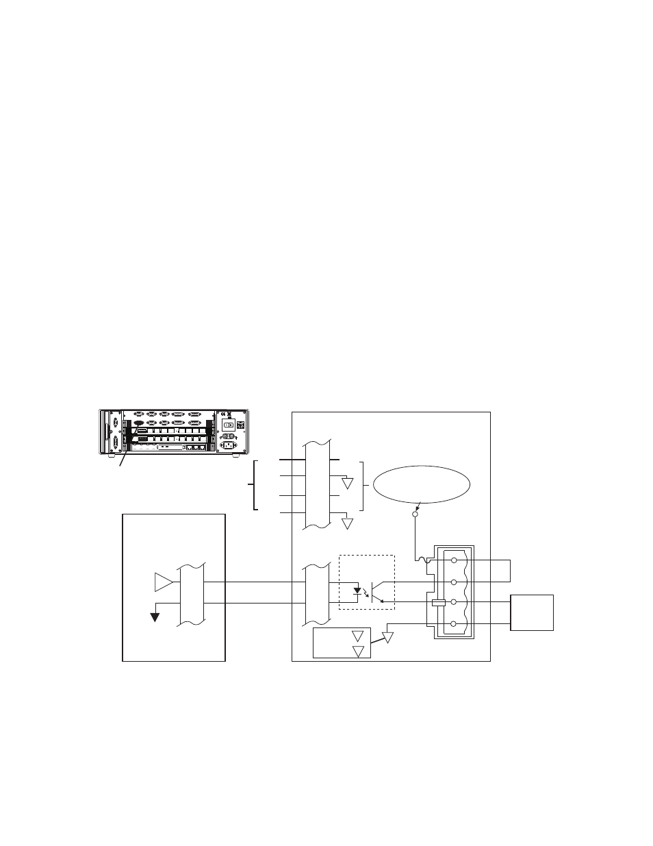
Digital Output Connections for the Model 494.32 DI/O Breakout Box
Output signals from the Model 494.44 System Board drive high-current
opto-isolators on the DI/O breakout box. These high-current opto-isolators
supply the higher voltage and current required by output devices.
Device connections
Each output device connects to a terminal plug that is inserted into one of the
eight output sockets on the DI/O breakout box.
Power connections
You can connect up to two output power sources to connector J29 Output
Power. When two power sources are used, outputs 1-4 are powered by one
source and outputs 5-8 are powered by the other source. These supply
voltages are internally wired to pins 1 and 4 of each of the eight input
sockets.
Output fuses
Each output connection includes a replaceable 3-amp fuse.
Model 494.44 System
Board connections
A cable from the J55 Dig Out connector on the Model 494.44 System Board
connects all eight digital-output signals to connector J20 Digital Outputs on
the DI/O breakout box.
External
DC Voltage
Source(s)
(30 V DC max.)
DO X
494.44 System Board
J55
Dig Out
x
9
J20
Digital
Outputs
x
9
High-Current
Opto-Isolator
494.32 DI/O Breakout Box
PWR 3
J29
Output Power
2
5
1
4
PWR 4
+
+
Outputs 1-4 use PWR 3
Outputs 5-8 use PWR 4
3
4
+
1
2
3
4
3
PWR 3 =
PWR 4 =
4
External
Device
Power
100-240 VAC
50-60 Hz, 1-2 A
DA Output
J24
1 2 3 4 5 6 7 8
1 2 3 4 5 6 7 8
LAN 2
LAN 1
DEBUG
MOT
OROLA
10/100 BASE T 10/100 BASE T
SCSI
BUSY
PIB
BUSY
PCI MEZZANINE CARD
PCI MEZZANINE CARD
J55 Dig Out
Dig In J54
J43A
J43B
J49
Aux Pwr
Estop/Run J23
Interlock
J29A
J29B
Load Frame
J28 HSM
A-B
HPU J25
J55
Dig Out
External
Jumper