Cable specification – MTS FlexTest Models 200 User Manual
Page 63
Model 494.41 Single-Station System Board
MTS FlexTest® Models 40/60/100/200 Controller Hardware
FlexTest Controller Configurations
63
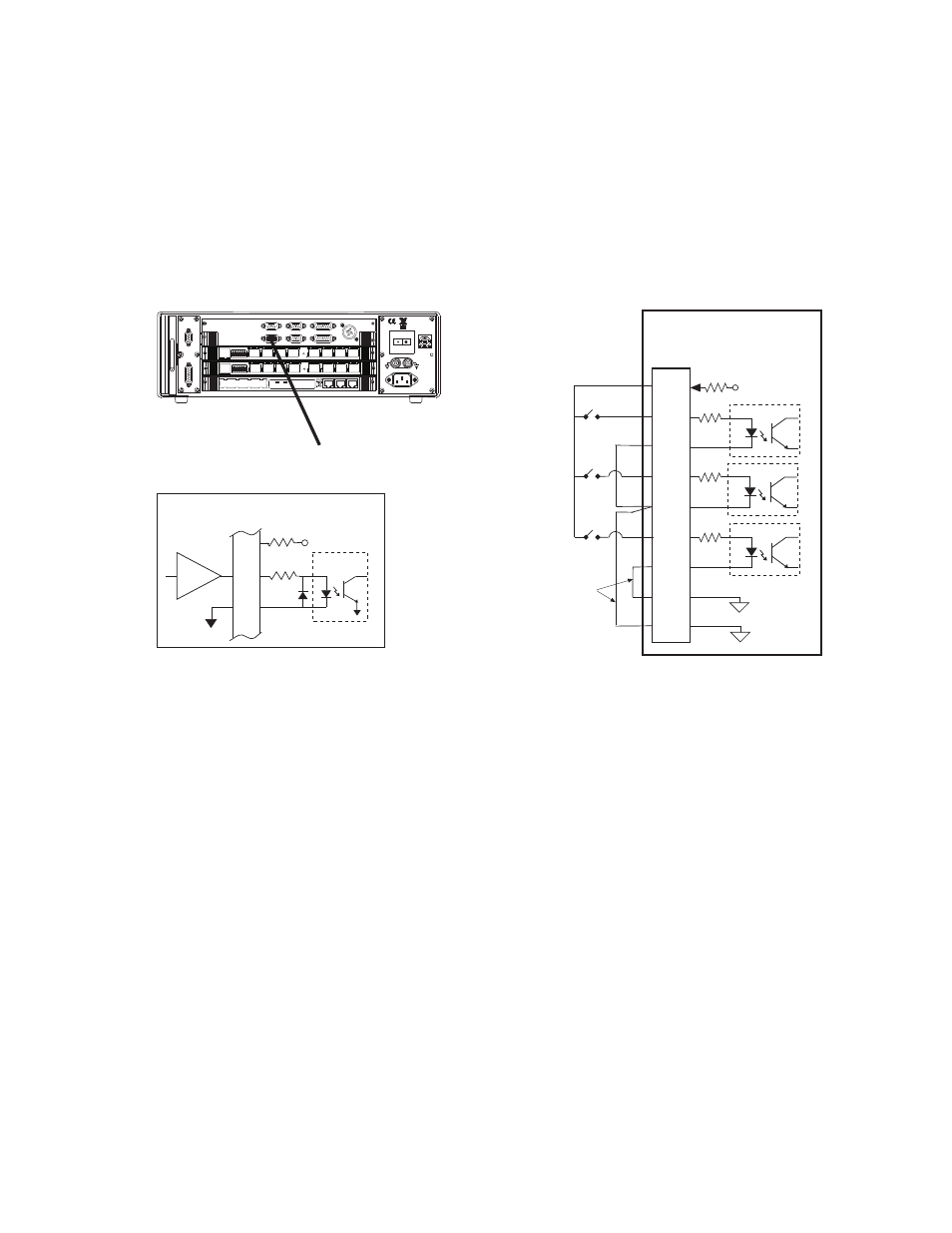
J54 Digital Input Connections for the Model 494.41 System Board
Connector J54 Dig In accepts up to three optically isolated digital-input signals
from external devices. You can use these digital input signals to trigger test
events in controller applications.
Cable specification
To maintain EMC compliance, the J54 Digital Input cable must comply with the
following specifications:
Connector type–9-pin, type D, male EMI connector.
Back shell–EMI metallized plastic or metal.
Cable–AWG and number of conductors as required. Braided shield with the
shield connected to the metallized backshell at the chassis.
494.41 System Board
Power
100-240 VAC
50-60 Hz, 1-2 A
DA Output
J24
1 2 3 4 5 6 7 8
1 2 3 4 5 6 7 8
J54 Dig In
J49
Aux Pwr
J25 Hpu
Dig Out J55
Intlk J43
E-stop J29
J28 HSM
LAN 2
LAN 1
DEBUG
MOT
O
ROLA
10/100 BASE T 10/100 BASE T
SCSI
BUSY
PIB
BUSY
PCI MEZZANINE CARD
PCI MEZZANINE CARD
J54 Digital Input
Logic Input Wiring
1
2
3
4
5
6
7
8
9
J54
Dig In
Input 1
+24 V
Low side of Opto
Inputs must be
jumpered to
ground. Use 22
AWG Jumper Wire.
Switch
or dry
contacts
Input 3
Input 2
+24 V DC
Opto-
Coupler
1
2
3
J54
External
Device