Cable specification, Load frame j29 – MTS FlexTest Models 200 User Manual
Page 77
Model 494.42 Single-Station System Board
MTS FlexTest® Models 40/60/100/200 Controller Hardware
FlexTest Controller Configurations
77
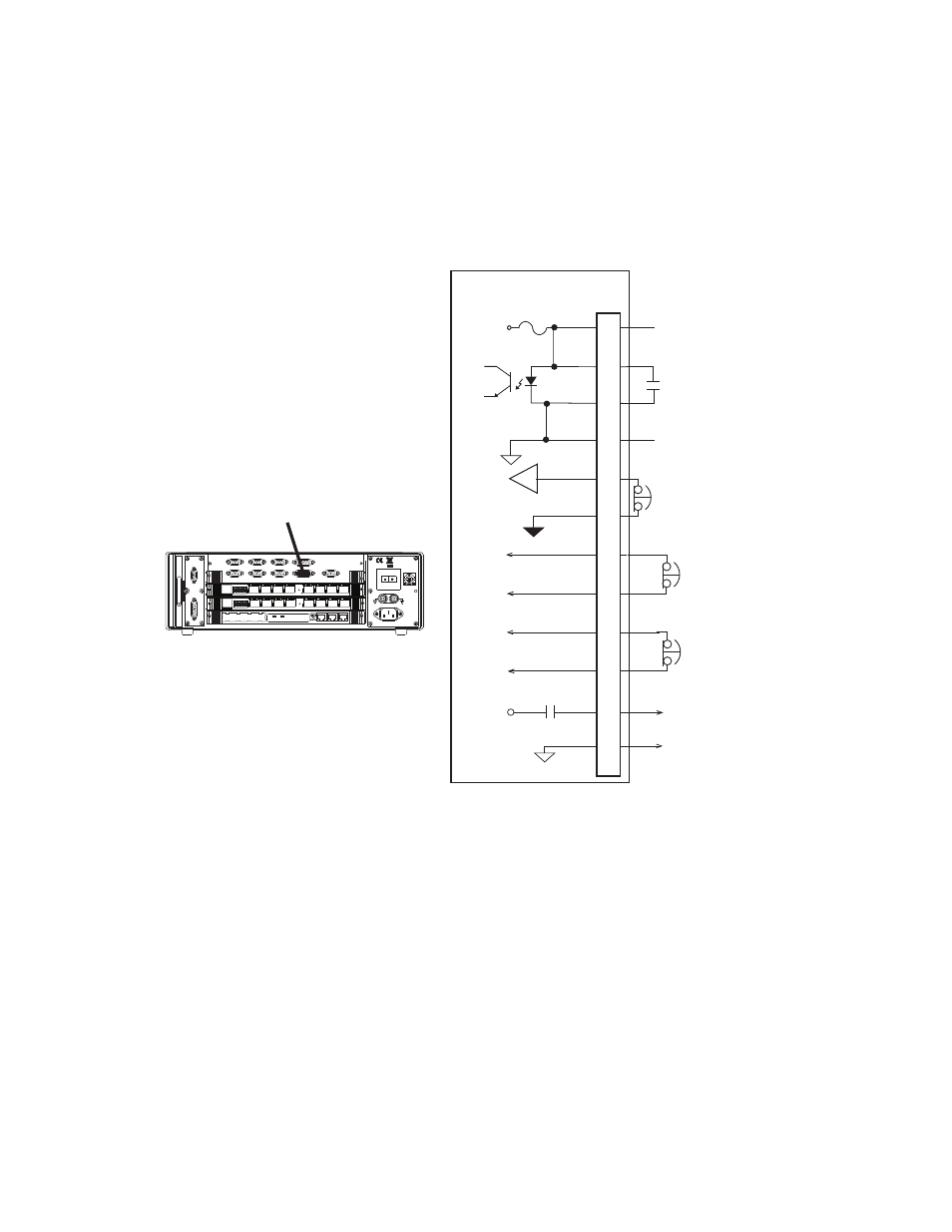
J29 Load Frame Connections for the Model 494.42 System Board
Connector J29 Load Frame provides an interface to connect one load frame.
Cable specification
To maintain EMC compliance, the J29 Load Frame cable must comply with the
following specifications:
Connector type–15-pin, type D, male EMI connector.
Backshell–EMI metallized plastic or metal.
Cable–18 AWG 8-conductor with foil shield, with the drain wire connected to a
metallized plastic backshell at the chassis.
HPU E Stop 2*
To HPU E Stop Chain
Controller Interlock
Open = Controller Interlock
494.42 System Board
Fused 24 V DC
to Crosshead
J29
1
4
3
2
7
5
8
13
11
15
12
14
Crosshead Interlock
Common
+24V
External Program
Interlock Source
Open=Program Interlock
To HPU E Stop Chain
HPU E Stop 1
+24V
HSM High
Crosshead Unlock Power
Crosshead Unlock
Power Common
Load Frame
J29
Pins 6,9,10 Reserved
Power
100-240 VAC
50-60 Hz, 1-2 A
DA Output
J24
1 2 3 4 5 6 7 8
1 2 3 4 5 6 7 8
LAN 2
LAN 1
DEBUG
MOT
O
ROLA
10/100 BASE T 10/100 BASE T
SCSI
BUSY
PIB
BUSY
PCI MEZZANINE CARD
PCI MEZZANINE CARD
J54
Dig In
J55 Dig Out
J43 INTLK
J56 UPS
J49
Aux Pwr
J23 Estop/Run
J29 Load Frame
J25 HPU
J28 HSM
* MTS Model 505 Pumps and older do not use the
HPU E-Stop 2 signal.