Model 494.25 single duc card pin assignments – MTS FlexTest Models 200 User Manual
Page 156
MTS FlexTest® Models 40/60/100/200 Controller Hardware
Model 494.25 Single DUC Card
Mezzanine Cards
156
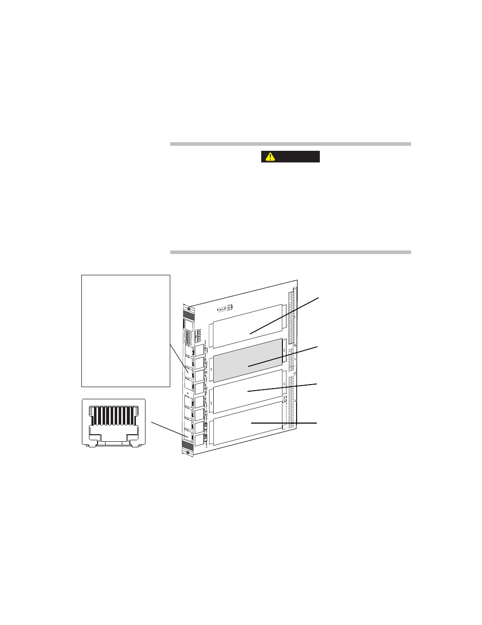
Model 494.25 Single DUC Card Pin Assignments
Signals are routed to and from each conditioner through an RJ-50 connector
located on the front of the I/O carrier board.
The front-panel sockets on the I/O carrier board only accept cabling
with 10-pin, shielded, RJ-50 connectors with a gray boot.
The use of other RJ connector types (less than 10 pins or unshielded
with a black boot) with the I/O carrier board can cause component
damage.
Only use transducer cables equipped with 10-pin, braided shield, RJ-50
connectors (with a gray boot) with the I/O carrier board.
CAUTION
Conditioner A
Pin 1 + IEEE 1451.4 Class 2
Pin 2 +EX
Pin 3 -EX
Pin 4 -FB
Pin 5 +FBR
Pin 6 -FBR
Pin 7 +FB
Pin 8 -EXS
Pin 9 +EXS
Pin 10 - IEEE 1451.4 Class 2
1
2
3
4
5
6
7
8
J1A
J1B
J2A
J2B
J3A
J3B
J4A
J4B
Cable Grounding
1 The cable shield connects to the metal shielding on the RJ-50 cable plug.
2 The cable plug shielding connects to the I/O Carrier Board body.
3 The I/O Carrier Board body connects to earth ground through the chassis.
RJ-50 Pin Assignments
(front view)
1 2 3 4 5 6 7 8 9 10
Card Slot 1
uses RJ-50 connectors
J1A and J1B
Card Slot 2
uses RJ-50 connectors
J2A and J2B
Card Slot 3
uses RJ-50 connectors
J3A and J3B
Card Slot 4
uses RJ-50 connectors
J4A and J4B