MTS FlexTest Models 200 User Manual
Page 223
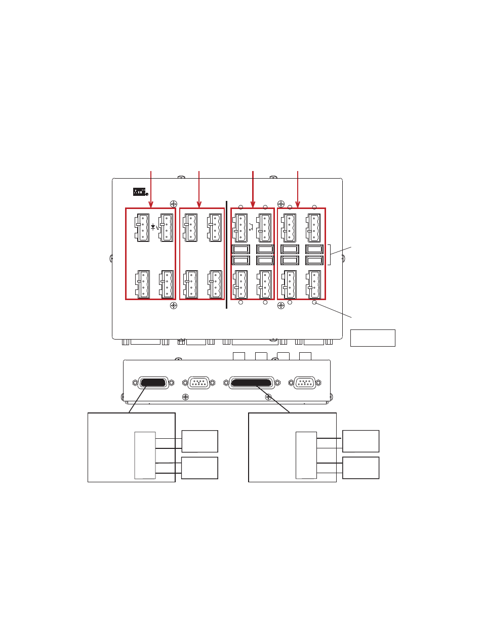
Model 494.32 8-Channel DI/O Breakout Box
MTS FlexTest® Models 40/60/100/200 Controller Hardware
Digital I/O and Transition Boards
223
Power Connections for the Model 494.32 DI/O Breakout Box
Input and output channels are grouped into banks that can be independently
powered.
DI/O Breakout Box
J19 Input Power
11
13
3
6
Input Bank 1
Power 1(J19)
Inputs 1-4
Input Bank 2
Power 2 (J19)
Inputs 5-8
Output Bank 1
Power 3 (J29)
Outputs 1-4
Output Bank 2
Power 4 (J29)
Outputs 5-8
Output
Fuses
(8x)
Output
Fuse-Status
LEDs (8x)
Input Bank 1
(Power 1)
Inputs 1-4
Input Bank 2
(Power 2)
Inputs 5-8
External
Power
Supply
External
Power
Supply
+
-
+
-
J29 Output Power
2
5
1
4
Output Bank 1
(Power 3)
Outputs 1-4
Output Bank 2
(Power 4)
Outputs 5-8
External
Power
Supply
External
Power
Supply
+
-
+
-
DI/O Breakout Box
LED
ON =
Fuse
Good
Input Power J19
Digital Inputs J10
Output Power J29
Digital Outputs J20
494.32
Digital I/O Channels
Inputs
Outputs
DI1
DI3
DI5
DI7
DI2
DI4
DI6
DI8
+ IN
PWR
- IN
PWR
DO2
DO4
DO6
DO8
1
2
3
4
DO1
DO3
DO5
DO7
+ OUT
PWR
- OUT
PWR
1
2
3
4