Transition card cage vme card cage – MTS FlexTest Models 200 User Manual
Page 273
Model 494.79 8-Channel Valve Driver Board
MTS FlexTest® Models 40/60/100/200 Controller Hardware
Digital I/O and Transition Boards
273
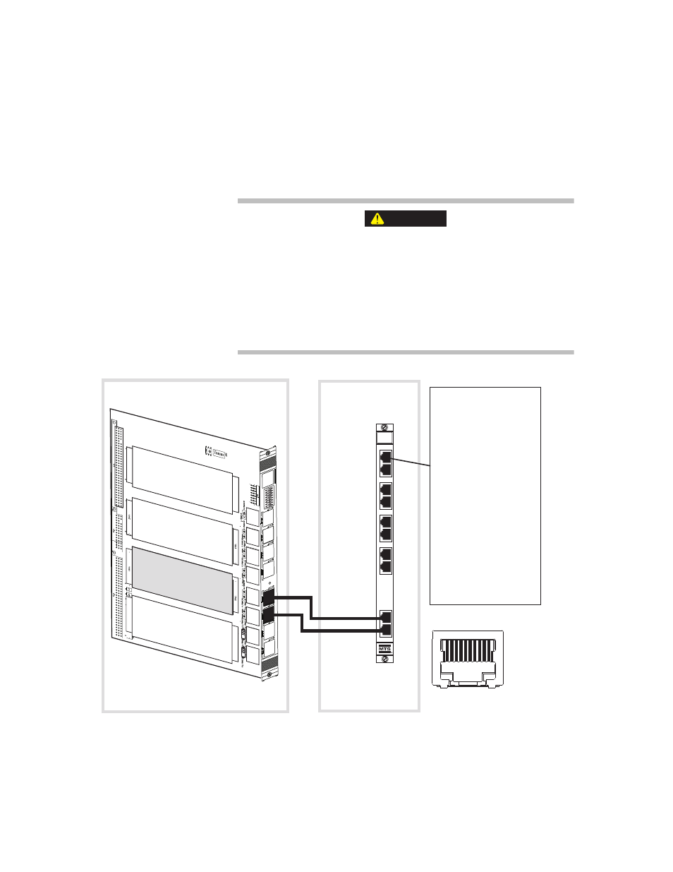
Model 494.79 8-Channel Valve Driver Board Pin Assignments
The following figure shows the pin assignments for each of the eight valve
driver outputs.
The front-panel sockets on the Model 494.79 board only accept cabling
with 10-pin, shielded, RJ-50 connectors with a gray boot.
The use of other RJ connector types (less than 10 pins or unshielded
with a black boot) with the Model 494.79 board can cause component
damage.
Only use transducer cables equipped with 10-pin, braided shield, RJ-50
connectors (with a gray boot) with the Model 494.79 board.
CAUTION
1
2
3
4
5
6
7
8
Model 494.79
8-Channel Valve
Driver transition board
Model 494.40 I/O Carrier board
Transition
Card Cage
VME Card Cage
J1A
J1B
J2A
J2B
J3A
J3B
J4A
J4B
494.79
8 CHANNEL
UNVERSAL
DRIVER
INPUT 1-4
INPUT 5-8
J
1
1
J
1
2
OUTPUT
J
9
J
1
0
OUTPUT
J
7
J
8
OUTPUT
J
5
J
6
OUTPUT
J
3
J
4
494.79 Valve Output RJ-50
Pin 1 Reserved
Pin 2 + Valve
Pin 3 - Valve
Pin 4 + Cable Loss*
Pin 5 - Cable Loss*
Pin 6 Reserved
Pin 7 Reserved
Pin 8 Reserved
Pin 9 Reserved
Pin 10 Reserved
Valve 1
Valve 2
Valve 3
Valve 4
Valve 5
Valve 6
Valve 7
Valve 8
494.46 8-Output
D/A Converter
Mezzanine Card
* Note: The two cable loss
detection lines (pins 4 and
5) must be shorted at the
valve connector.
1-4
5-8
RJ-50 Pin Assignments
(front view)
1 2 3 4 5 6 7 8 9 10