Single two-stage valve dual two-stage valves – MTS FlexTest Models 200 User Manual
Page 274
MTS FlexTest® Models 40/60/100/200 Controller Hardware
Model 494.79 8-Channel Valve Driver Board
Digital I/O and Transition Boards
274
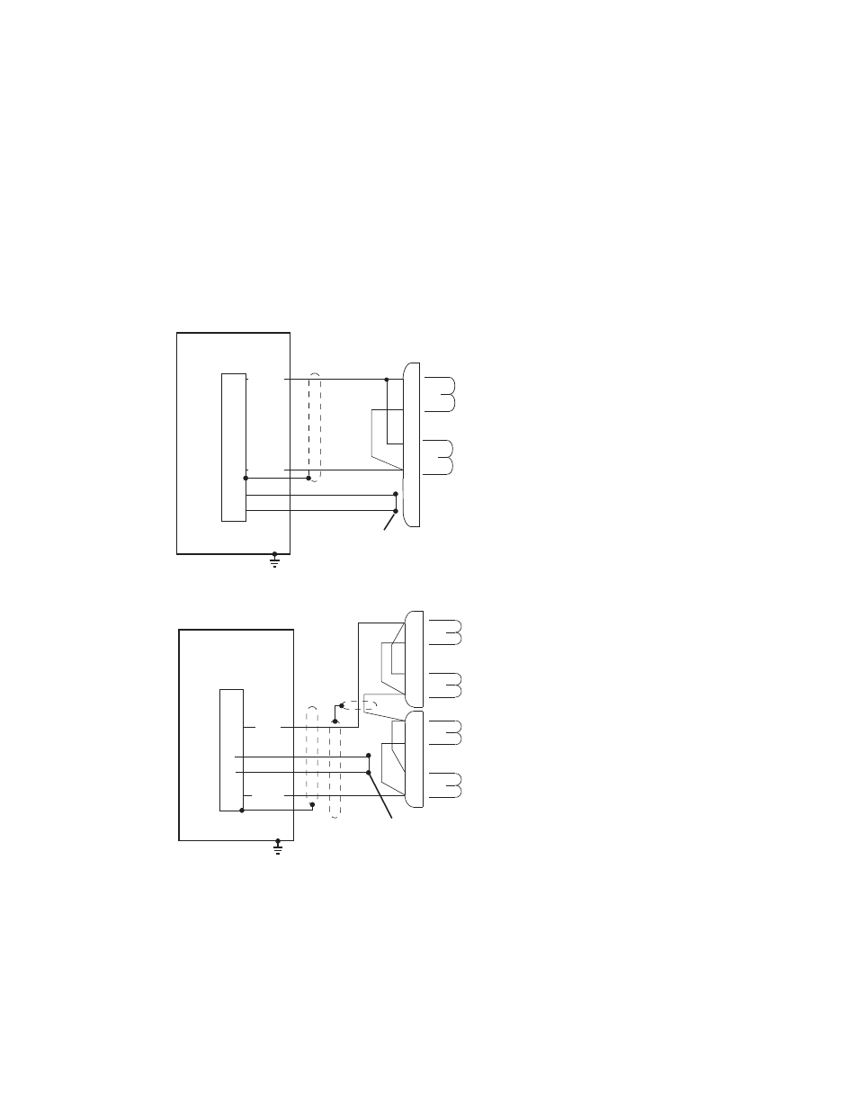
Two-Stage Servovalve Connections for the Model 494.79 Valve Driver
You can use the analog output signals from the D/A converter card to drive a
Model 494.79 8-Channel Valve Driver board. The transition board connects
to the D/A converter card through front-panel I/O carrier board connectors.
Note
The following diagrams show wiring for systems where compression
is positive.
Single two-stage valve
Dual two-stage valves
Cable Grounding
1 The cable shield connects to the
metal shielding on the RJ-50 cable
plug. (The two inputs use RJ-50
connectors.)
2 The cable plug shielding connects
to the I/O carrier board body.
3 The I/O carrier board connects to
earth ground through the chassis.
494.79 8-Channel
Valve Driver
Front-panel RJ-50
Connectors (J3 - J10)
JX
3
2
- VD
+ VD
A
B
C
D
Servovalve
4
5
Connect the cable-loss-detection lines
(pins 4 and 5) at the valve connector.
494.79 8-Channel
Valve Driver
Front-panel RJ-50
Connectors (J3 - J10)
JX
3
A
B
C
D
Servovalve
A
B
C
D
Servovalve
- VD
+ VD
2
Connect the cable-loss-detection
lines (pins 4 and 5) at the valve connector.
4
5
Cable Grounding
1 The cable shield connects to the
metal shielding on the RJ-50 cable
plug. (The two inputs use RJ-50
connectors.)
2 The cable plug shielding connects
to the I/O carrier board body.
3 The I/O carrier board connects to
earth ground through the chassis.