Cable specifications – MTS FlexTest Models 200 User Manual
Page 244
MTS FlexTest® Models 40/60/100/200 Controller Hardware
Model 493.73 HPU Interface Board
Digital I/O and Transition Boards
244
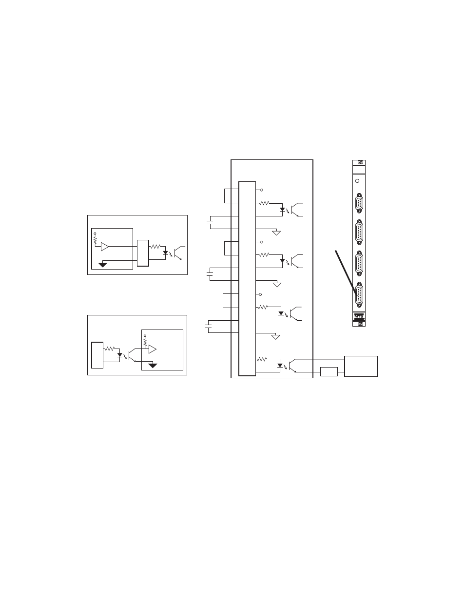
J54 DI/O Connections for the Model 493.73 HPU Interface Board
Connector J54 SYS DI/O provides three digital inputs and one digital
output. Inputs can be external switches or logic inputs. The inputs are
connected to the high and low inputs of an opto-isolator that includes a
debounce circuit for use with mechanical switch contacts.
Cable specifications
To maintain EMC compliance, J54 System I/O cables must comply with the
following specifications:
Connector–15-contact, type D, male EMI connector.
Backshell–EMI metallized plastic or metal.
Cable–AWG and number of conductors as required. Braided shield with
shield connected to the metallized backshell at the chassis.
+24 V DC
+24 V DC
+24 V DC
493.73
HPU Board
J54
SYS DI/O
SERVICE
493.73
HPU
J23
E-STOP OUT
J24
E-STOP IN
J25 HPU
J54
SYS D I/O
493.73
HPU Board
External
Power
Supply
External
Device
External
Device
Digital Output
Digital Input 3
1
2
3
4
5
6
7
8
9
10
11
12
13
14
15
J54
SYS DI/O
Digital Input 1
Digital Input 2
+
-
Load
Reserved
Open=Logic 1
Open=Logic 1
Open=Logic 1
Logic Output
14
15
J54
Logic Input
J54
14
15