Half-bridge configuration – MTS FlexTest Models 200 User Manual
Page 149
Digital Universal Conditioner Mezzanine Cards
MTS FlexTest® Models 40/60/100/200 Controller Hardware
Mezzanine Cards
149
Half-bridge
configuration
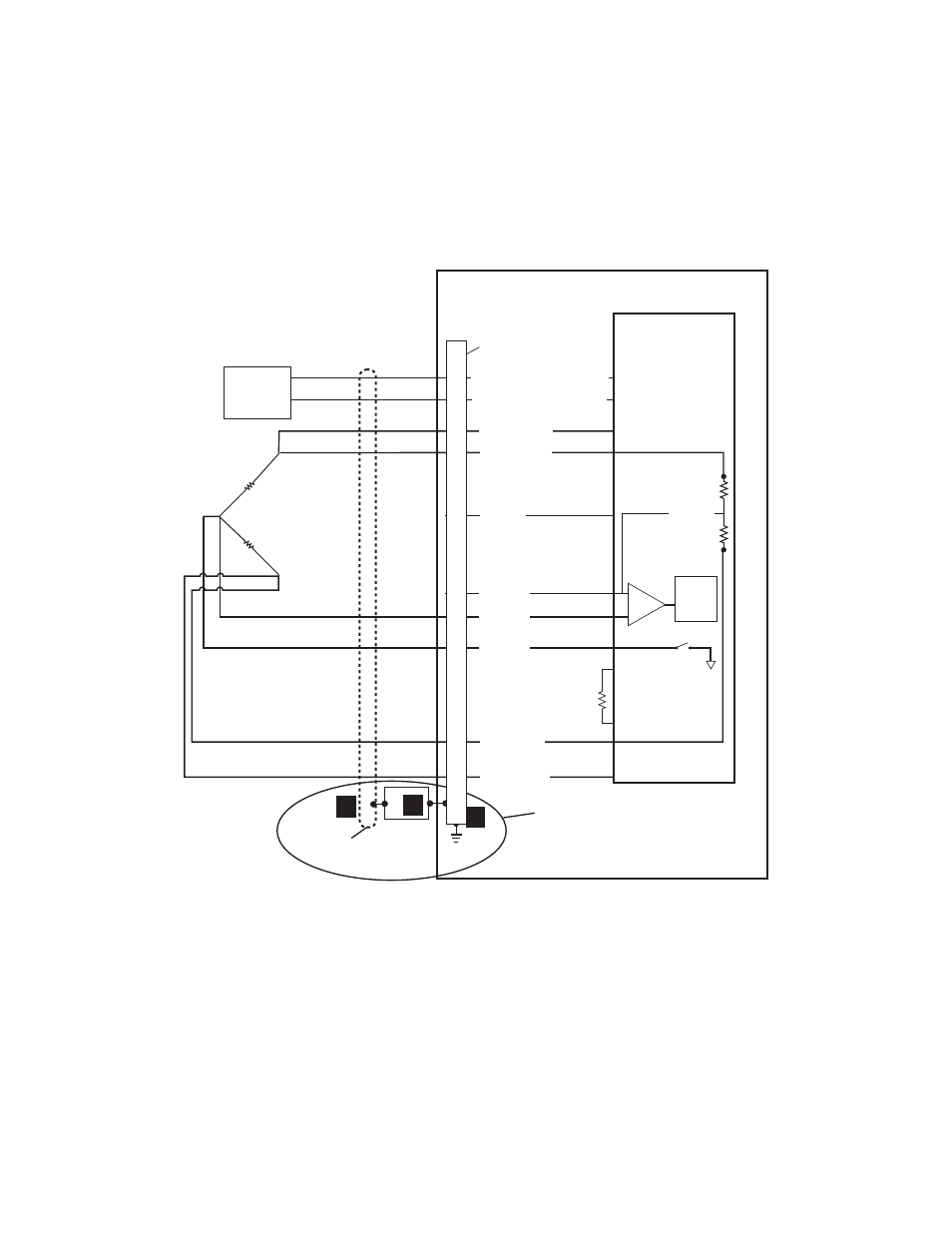
The following figure shows a half-bridge configuration. In this
configuration, the transducer makes up half of the bridge circuit while the
other half of the bridge is located on the DUC card.
IEEE
1451.4
Circuit
+ IEEE 1451.4 Class 2
-Ex
R
Shunt
-Ex Sense
I/O Carrier Board
Front-Panel
RJ-50
Connector
Transducer
RJ-50
Cable
Plug
2
1
Cable
Shield
3
Cable Grounding
1 The cable shield connects to the metal
shielding on the RJ-50 cable plug.
2 The cable plug shielding connects to the
I/O carrier board body.
3 The I/O carrier board connects to earth
ground through the chassis.
DUC
A to D
SW1B
+Excitation
-Excitation
+FB
-FB
-FBR
- IEEE 1451.4 Class 2
+Ex Sense
+FBR
-Ex Sense
6
4
7
5
9
2
3
8
10
1
Wagner
Voltage
Source