Aero multibox overview, About multibox systems, Aero multibox overview 294 – MTS FlexTest Models 200 User Manual
Page 294: Box 1, Box 2, Box 3, Cabling
MTS FlexTest® Models 40/60/100/200 Controller Hardware
Aero Multibox Overview
Aero Multibox Systems
294
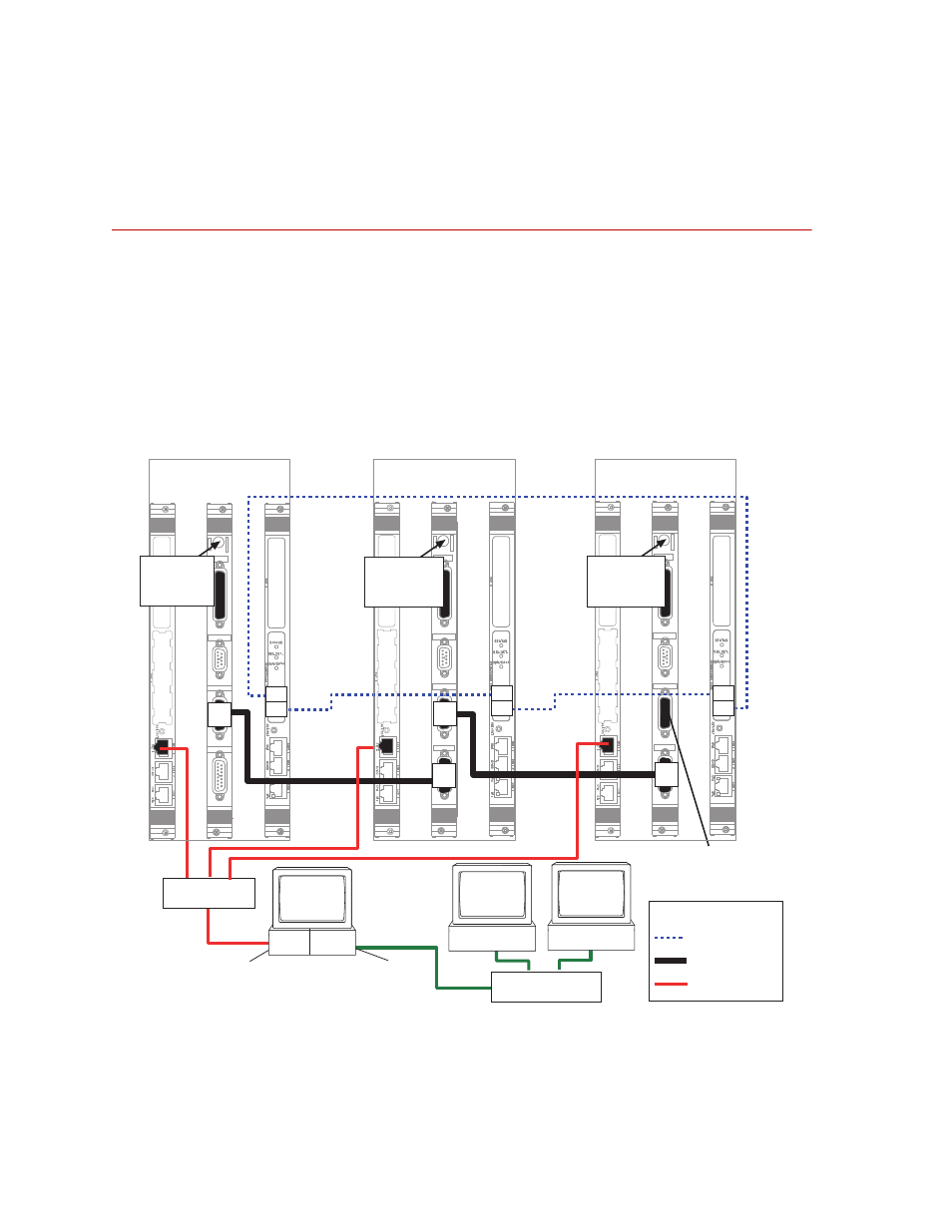
Aero Multibox Overview
About Multibox Systems
A multibox system consists of up to 12 networkable 20-slot controller chassis
(boxes) that can be combined to create various test systems.
•
Series 493 Hardware can provide up to 30 control channels per box for a
maximum of 360 control channels for a 12-box system.
•
Series 494 Hardware can provide up to 40 control channels per box for a
maximum of 480 control channels for a 12-box system.
B
O
X
A
D
R
S
J8 Intlk In
J9 Intlk Out
J51 Box In
J52 Box Out
B
O
X
A
D
R
S
J8 Intlk In
J9 Intlk Out
J51 Box In
J52 Box Out
B
O
X
A
D
R
S
J8 Intlk In
J9 Intlk Out
J51 Box In
J52 Box Out
Box 1
(Master
)
Box Out
Jumper
Plug
Box 2
(Dependant)
Box 3
(Dependant)
Gigabit Ethernet
Switch
Controller NIC Address
148.150.203.190
Subnet: 255.255.255.0
Gigabit Ethernet
Switch
Client NIC Address
172.16.20.100
Subnet: 255.255.255.0
Client 1
Client 2
Server
NIC
NIC
Box
Address
Switch = 0
148.150.203.8
RX
TX
RX
TX
RX
TX
Box
In
Box
Out
Box
Out
Box
In
Box
Address
Switch = 1
148.150.203.16
Box
Address
Switch = 2
148.150.203.24
172.16.20.101
172.16.20.102
Fiber Optic
Interlock Chain
Ethernet
Cabling