MTS FlexTest Models 200 User Manual
Page 201
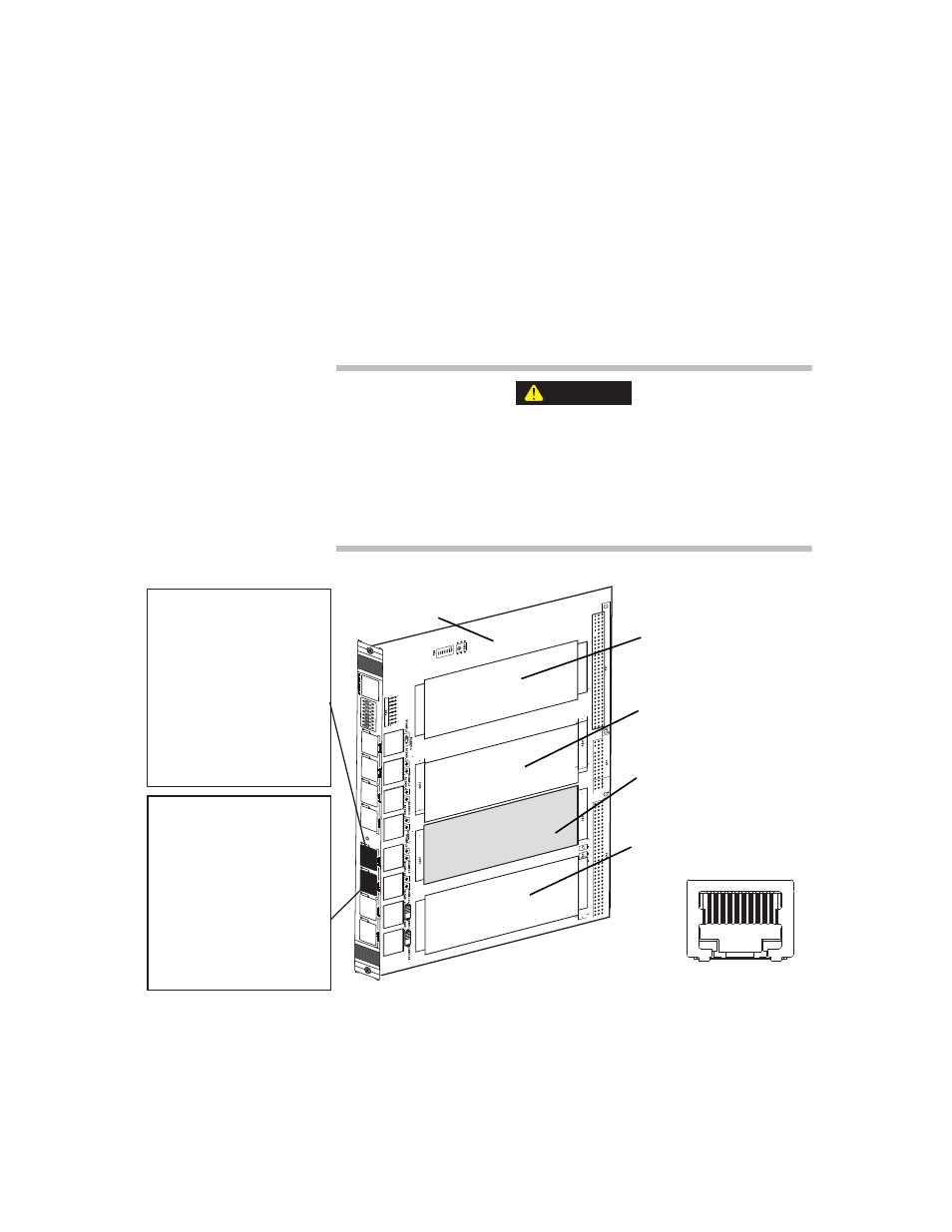
Model 494.49 Quad Encoder Interface Card
MTS FlexTest® Models 40/60/100/200 Controller Hardware
Mezzanine Cards
201
SSI/Gurley Encoder Pin Assignments for the Model 494.49 Card
The device type that you set in your hardware-mapping software determines
the pin assignments. The following figure shows the pin assignments for SSI
devices (such as Temposonics R transducers).
Note
Signals are routed to and from the Quad Encoder card through two
RJ-50 connectors located on the front of the I/O carrier board.
The front-panel sockets on the I/O carrier board only accept cabling
with 10-pin, shielded, RJ-50 connectors.
The use of other RJ connector types (less than 10 pins or unshielded)
with the I/O carrier board can cause component damage.
Only use cables equipped with 10-pin, braided shielded, RJ-50 connectors
(with gray boot) with the I/O carrier board.
CAUTION
Device 1 and 2
Pin 1 + IEEE 1451.4, Class 2
Pin 2 Data (Chan 1)
Pin 3 Intg (Chan 1)
Pin 4 Clock (Chan 1)
Pin 5 Digital Ground
Pin 6 Data (Chan 2)
Pin 7 Intg (Chan 2)
Pin 8 Clock (Chan 2)
Pin 9 Digital Ground
Pin 10 - IEEE 1451.4, Class 2
1
2
3
4
5
6
7
8
RJ-50 Pin Assignments
(front view)
J1A
J1B
J2A
J2B
J3A
J3B
J4A
J4B
494.49 Quad Encoder
Mezzanine Card
1 2 3 4 5 6 7 8 9 10
Device 3 and 4
Pin 1 + IEEE 1451.4, Class 2
Pin 2 Data (Chan 3)
Pin 3 Intg (Chan 3)
Pin 4 Clock (Chan 3)
Pin 5 Digital Ground
Pin 6 Data (Chan 4)
Pin 7 Intg (Chan 4)
Pin 8 Clock (Chan 4)
Pin 9 Digital Ground
Pin 10 - IEEE 1451.4, Class 2
Card Slot 1
uses RJ-50 connectors
J1A and J1B
Card Slot 2
uses RJ-50 connectors
J2A and J2B
Card Slot 3
uses RJ-50 connectors
J3A and J3B
Card Slot 4
uses RJ-50 connectors
J4A and J4B
Model 494.40 I/O
Carrier Board