Breakout box connections, Di/o board connections – MTS FlexTest Models 200 User Manual
Page 220
MTS FlexTest® Models 40/60/100/200 Controller Hardware
Model 494.31 16-Channel High-Current DI/O Breakout Box
Digital I/O and Transition Boards
220
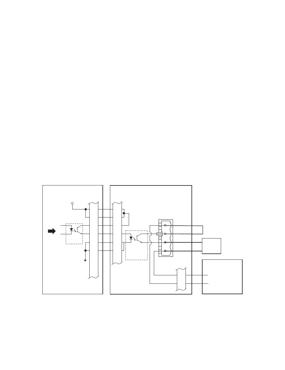
Digital Output Connections for the Model 494.31 Breakout Box
The J4 Out connector provides up to sixteen digital output signals that can
control external devices. These digital-output signals are controlled by
controller software.
Breakout box
connections
Device connections–each output device connects to a terminal plug that is
inserted into one of the 16 output sockets on the digital I/O breakout box.
Power connections–you can connect an external power supply to connector
J21. This supply voltage is distributed to each of the 16 output sockets on
the digital I/O breakout box.
High-current, power-switching circuits–each digital output includes a
power MOSFET that is controlled by the corresponding opto isolator on the
Model 493.72 Digital I/O board. Each output MOSFET is rated for a
maximum of 30 V DC and 2 A.
DI/O board connections
A cable from J4 on the Model 493.72 Digital I/O board connects all 16
digital-output signals to connector J20 on the Digital I/O Breakout box.
Each digital output on the Model 493.72 board has an opto isolator that
controls the corresponding power MOSFET on the digital I/O breakout box.
J4
OUT
494.31 DI/O Breakout Box
J21
OUTPUT
PWR
1
20
4
1
- Output Power*
+ Output Power*
External
Power Supply
* 30 V DC maximum
J20
OUT
1
20
+12 V DC
493.72 Digital I/O
Transition Board
Opto-
Isolator
Jumper
External
Device
High-Current
Solid-State
Relay
+ Output 1
- Output 1
18
19
18
19
36
37
36
37
From
Controller