Jumper plug required, Cable specification, 44 system board – MTS FlexTest Models 200 User Manual
Page 95: J43 intlk, Interlock j43a j43b
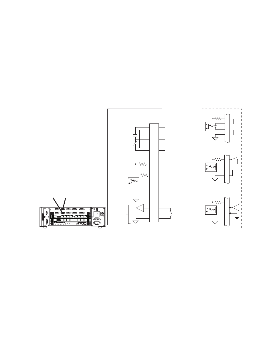
Model 494.44 Two-Station System Board
MTS FlexTest® Models 40/60/100/200 Controller Hardware
FlexTest Controller Configurations
95
Jumper plug required
If connector J29 is not used, you must install a jumper plug to maintain the
integrity of the interlocks. Use jumper plug part number 100-007-947 or jumper
pins: 3-4, 5-7, 8-13, and 11-15.
J43 A/B Interlock Connections for the Model 494.44 System Board
Connector J43 A/B Interlock provides one optically isolated interlock input and
a relay-contact interlock output per connector.
Cable specification
To maintain EMC compliance, the J43 Interlock cable must comply with the
following specifications:
Connector type–9-pin, type D, male EMI connector.
Backshell–EMI metallized plastic or metal.
Cable–shielded twisted pairs (24 AWG minimum), braided shield with shield
connected to the metallized backshell at the chassis.
Event Input
+24V
1
2
3
4
Interlock Disabled
+24V
1
2
3
4
Switch Contact
(Open = Interlock)
+24V
1
2
3
4
Logic Input
(0=Interlock)
Interlock In (Gnd)
Interlock Out (NO)
Interlock = Open
Interlock Out (NC)
Interlock = Closed
Common
- Interlock In
+ Interlock In
Interlock In (Pwr)
+24V
J43
Intlk
494.44 System Board
6
7
8
1
2
3
4
5
9
Interlock
Output
Interlock
Input
Interlock
J43A J43B
Power
100-240 VAC
50-60 Hz, 1-2 A
DA Output
J24
1 2 3 4 5 6 7 8
1 2 3 4 5 6 7 8
LAN 2
LAN 1
DEBUG
MOT
OROLA
10/100 BASE T 10/100 BASE T
SCSI
BUSY
PIB
BUSY
PCI MEZZANINE CARD
PCI MEZZANINE CARD
J55 Dig Out
Dig In J54
J43A
J43B
J49
Aux Pwr
Estop/Run J23
Interlock
J29A
J29B
Load Frame
J28 HSM
A-B
HPU J25
Software
Defined