Cable specification, Jumper plug required, J24 e-stop – MTS FlexTest Models 200 User Manual
Page 89
Model 494.44 Two-Station System Board
MTS FlexTest® Models 40/60/100/200 Controller Hardware
FlexTest Controller Configurations
89
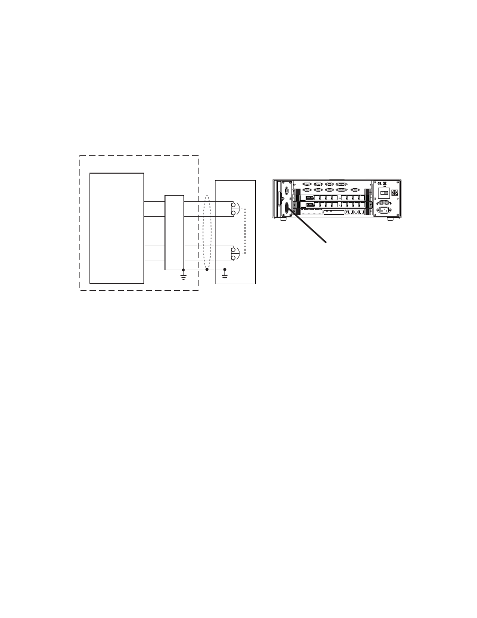
J24 Emergency Stop Connections for the Model 494.44 System Board
The Model 494.44 System Board provides two optional E-Stop inputs that are
available on the J24 E Stop connector (located on the rear panel of the Model
494.04 Chassis).
Cable specification
To maintain EMC compliance, the J24 E-Stop cable must comply with the
following specifications:
Connector type–15-pin, type D, male EMI connector.
Backshell–EMI metallized plastic or metal.
Cable–24 AWG 4-conductor with braided shield, with the braid connected to a
metallized plastic backshell at the chassis and to ground at the emergency stop
(E-Stop) box.
Jumper plug required
If connector J24 is not used, you must install a jumper plug to maintain the
integrity of the interlocks. Use jumper plug part number 039-713-201 or jumper
pins 5-7 and 8-13.
494.04 Chassis
494.44 System
Board
J24 E-Stop
Power
100-240 VAC
50-60 Hz, 1-2 A
DA Output
J24
1 2 3 4 5 6 7 8
1 2 3 4 5 6 7 8
LAN 2
LAN 1
DEBUG
MOT
O
ROLA
10/100 BASE T 10/100 BASE T
SCSI
BUSY
PIB
BUSY
PCI MEZZANINE CARD
PCI MEZZANINE CARD
J54
Dig In
J55 Dig Out
J43 INTLK
J56 UPS
J49
Aux Pwr
J23 Estop/Run
J29 Load Frame
J25 HPU
J28 HSM
J24
8
13
5
7
E-Stop Box