Troubleshooting and maintenance, Chassis troubleshooting, J39 service test points – MTS FlexTest Models 200 User Manual
Page 285: Appendix a, Troubleshooting and maintenance 285, Chassis troubleshooting 285
Troubleshooting and Maintenance
MTS FlexTest® Models 40/60/100/200 Controller Hardware
Troubleshooting and Maintenance
285
Appendix A
Troubleshooting and Maintenance
Chassis Troubleshooting
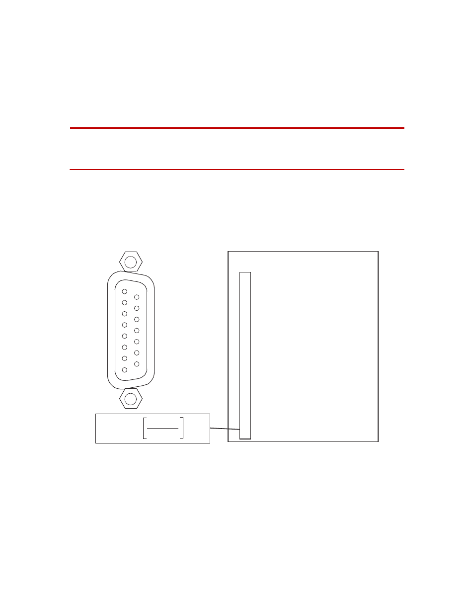
J39 Service Test Points
The J39 Power Monitor connector (located on the rear panel of the Model
494.06, 494.10, and 494.20 Chassis) provides service test points. Test points
include all of the power supply voltages and the status of the
overtemperature sensor and the power-fail circuit.
Note
Each output signal on the J39 connector includes a 2 K-ohm
current-limiting resistor. These outputs cannot provide enough
current to drive external devices. Do not connect external devices
(other than high-impedance test equipment) to the J39 connector.
494.xx Chassis
J39 Power Monitor
2
+ 5 V DC
3
+ 12 V DC
4
- 12 V DC
5
+ 15 V DC
6
- 15 V DC
7
+ 24 V DC
8
AGND
9
2.5 V Ref
10
+ 5 V AC Fail
11
AGND
12
+ 24 V AC Fail
13
Over Temp (TTL 0 = Overtemp condition)
14
Internal Chassis Temperature*
15
Power Fail (TTL 0 = Power failure)
* Temperature =
(degrees C)
Vout (pin 14)
0.005
- 273.15
1
8
9
15