Cable specification, Jumper plug – MTS FlexTest Models 200 User Manual
Page 251
Model 493.74 Two-Station HSM Interface Board
MTS FlexTest® Models 40/60/100/200 Controller Hardware
Digital I/O and Transition Boards
251
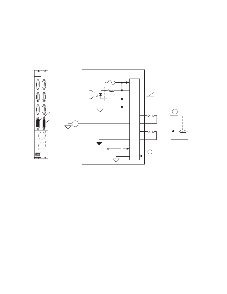
J29 Load Frame Connections for the Model 493.74 HSM Board
Connector J29 Load Frame connects to the load unit control module. Load
frame signals include E-Stop and crosshead controls for each station.
Cable specification
To maintain EMC compliance, J29 Load Frame cables must comply with
the following specifications:
Connector–15-contact, type D, male EMI connector with conductive
backshell.
Cable for load frames with crosshead locks built after 1985–18 AWG, 8
conductor with overall foil shield with drain wire connected to the
conductive backshell.
Cable for all load frames without crosshead locks–22 AWG, 6 conductor
with overall foil shield with drain wire connected to the conductive
backshell.
Jumper plug
If connector J29 is not used, you must install a jumper plug to maintain the
integrity of the interlocks. Use jumper plug part number 100-007-947 or
jumper pins: 3 and 4; 5 and 7; 11 and 15; 8 and 13.
Cross Head Unlock
493.74 HSM Board
J29A
J29B
Intlk
J28B HSM
R
J43-1
J43-2
Run/Stop
J44-1
J44-2
Aux Power
J49-1
J49-2
Load Frame
J29-1
J29-2
J28A HSM
493.74
HSM
Station
Emergency
Stop
Crosshead
Unlock
Input
DC Common
HSM Hi
Crosshead
Solenoid
+24 V
Station
Interlock
CRM
Relay
in HPU
J29
Load Frame
1
4
3
2
13
8
7
5
12
14
To Load Unit
Control Module
HSM High=Unlock Enabled
Open=Program
Interlock
Note: Pins 11 and 15 are reserved
+24 V DC
+24 V DC
OR Station
Stop