Breakout box connections – MTS FlexTest Models 200 User Manual
Page 219
Model 494.31 16-Channel High-Current DI/O Breakout Box
MTS FlexTest® Models 40/60/100/200 Controller Hardware
Digital I/O and Transition Boards
219
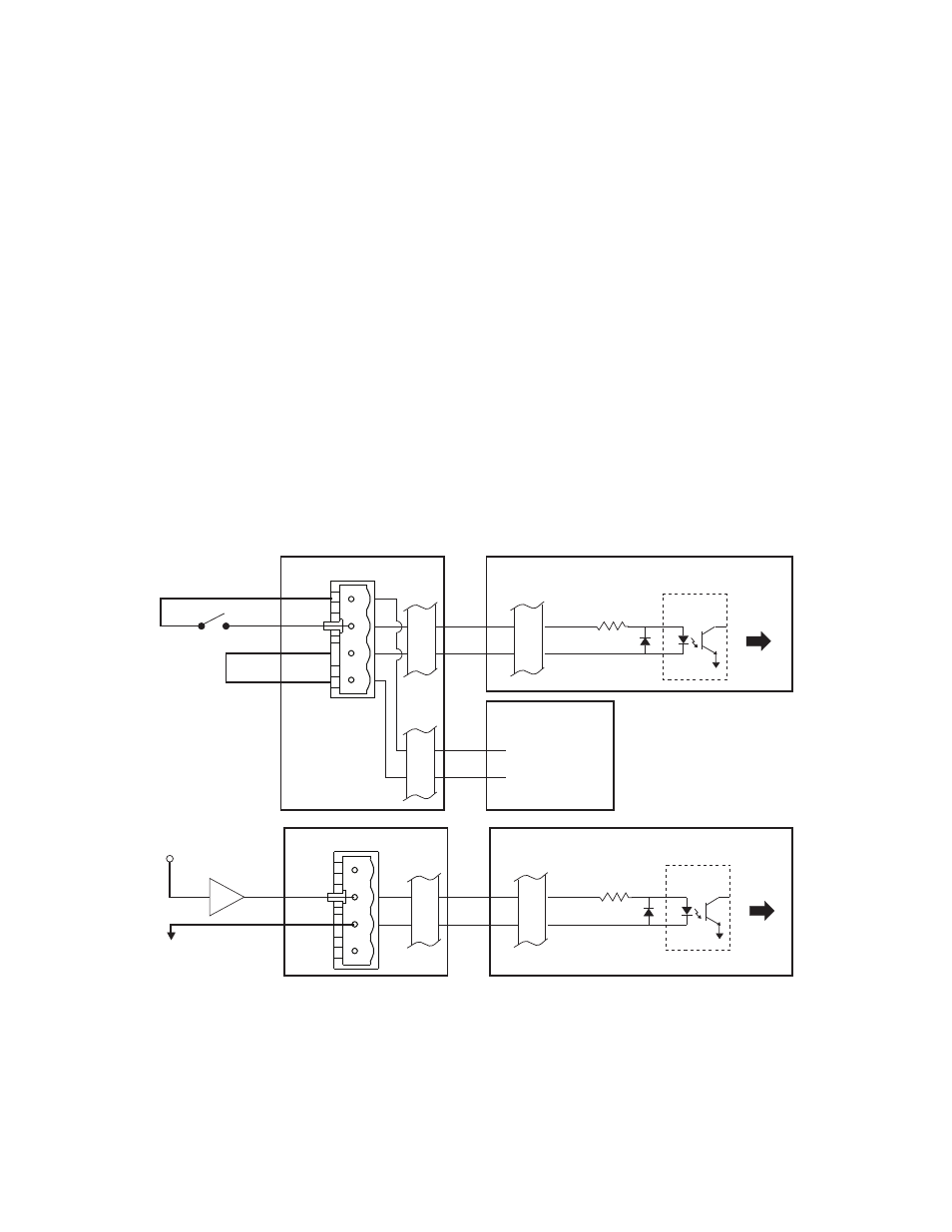
Digital Input Connections for the Model 494.31 DI/O Breakout Box
The J3 In connector accepts up to sixteen digital-input signals from external
devices. These signals are monitored by controller software.
Breakout box
connections
Device connections–each input device connects to a terminal plug that is
inserted into one of the 16 input sockets on the D I/O breakout box.
Power connections–if required, you can connect an external power supply
to connector J11. This supply voltage is distributed to each of the 16 input
sockets on the Model 494.31 DI/O Breakout Box.
Model 493.72 Digital I/O
board connections
A cable from J10 on the DI/O breakout box connects all 16 input-device
signals to J3 on the Model 493.72 board. Each digital input on the Model
493.72 board has an opto isolator that is controlled by the input device.
Note
Digital inputs have 20-ms debounce circuits. If required, you install
jumpers on the Model 493.72 Digital I/O board to shorten the
debounce times.
J3
IN
+Input1
-Input 1
External Switch
or
Relay Contact
494.31 DI/O Breakout Box
J10
IN
1
20
J11
INPUT
PWR
1
20
1
3
+ Input Power*
- Input Power*
External
Power Supply
* 2.7 to 26 V DC
J3
IN
Logic Input
J10
IN
1
20
1
20
2.7 to 26 V DC
+Input1
-Input 1
Jumper
494.31 DI/O Breakout Box
493.72 Digital I/O Transition Board
Opto-
Isolator
493.72 Digital I/O Transition Board
Opto-
Isolator
To
Controller
To
Controller