Breakout box connections, For more information – MTS FlexTest Models 200 User Manual
Page 214
MTS FlexTest® Models 40/60/100/200 Controller Hardware
Model 493.31 16-Channel Low-Current DI/O Breakout Box
Digital I/O and Transition Boards
214
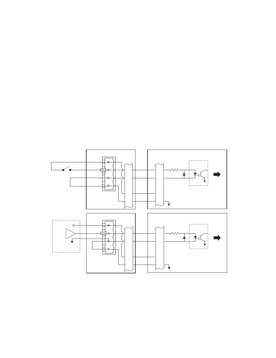
Digital Input Connections for the Model 493.31 DI/O Breakout Box
The J3 In connector on the Model 493.72 board accepts up to sixteen
digital-input signals from external devices that are connected to the Model
493.31 DI/O Breakout Box. These signals are monitored by controller
software.
Breakout box
connections
Each input device connects to a terminal plug that is inserted into one of the
16 input sockets on the D I/O breakout box.
Model 493.72 board
connections
A cable from J10 on the DI/O breakout box connects all 16 input-device
signals to J3 on the Model 493.72 board. Each digital input on the Model
493.72 board has an opto isolator that is controlled by the input device.
Note
Digital inputs have 20-ms debounce circuits. If required, install
jumpers on the Model 493.72 board to shorten the debounce times.
For more information
The connection drawings show pin assignments for input 1. For a complete
list of pin assignments, see
“Digital I/O Connections for the Model 493.31
J3 IN
External Switch
or
Relay Contact
493.31 DI/O Breakout Box
J10
IN
1
20
1
20
Jumper
18
36
+ 12 VDC
18
36
J3 IN
Logic Input Device
493.31 DI/O Breakout Box
J10
IN
1
20
1
20
Jumper
18
36
+ 12 VDC
18
36
+ 12 VDC
493.72 Digital I/O Transition Board
Opto-
Isolator
To
Controller
493.72 Digital I/O Transition Board
Opto-
Isolator
To
Controller