MTS FlexTest Models 200 User Manual
Page 198
MTS FlexTest® Models 40/60/100/200 Controller Hardware
Model 494.49 Quad Encoder Interface Card
Mezzanine Cards
198
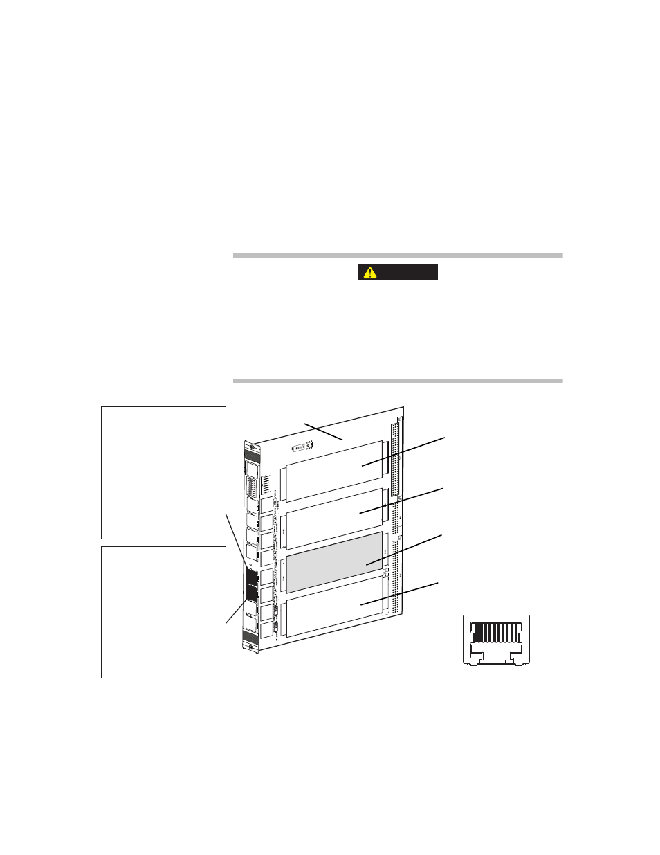
Incremental Encoder/Counter Pin Assignments for the Model 494.49 Card
The device type that you set in your hardware-mapping software determines
the pin assignments. The following figure shows the pin assignments for
incremental encoders with quadrature outputs.
Note
Signals are routed to and from the Quad Encoder card through two
RJ-50 connectors located on the front of the I/O carrier board.
The front-panel sockets on the I/O carrier board only accept cabling
with 10-pin, shielded, RJ-50 connectors.
The use of other RJ connector types (less than 10 pins or unshielded)
with the I/O carrier board can cause component damage.
Only use cables equipped with 10-pin, braided shielded, RJ-50 connectors
(with gray boot) with the I/O carrier board.
CAUTION
Encoder 1 and 2
Pin 1 + IEEE 1451.4 Class 2
Pin 2 A (Channel 1)
Pin 3 B (Channel 1)
Pin 4 Index (Channel 1)
Pin 5 Digital Ground
Pin 6 A (Channel 2)
Pin 7 B (Channel 2)
Pin 8 Index (Channel 2)
Pin 9 Digital Ground]
Pin 10 - IEEE 1451.4 Class 2
1
2
3
4
5
6
7
8
RJ-50 Pin Assignments (front view)
1 2 3 4 5 6 7 8 9 10
J1A
J1B
J2A
J2B
J3A
J3B
J4A
J4B
494.49 Quad Encoder
InterfaceMezzanine Card
Encoder 3 and 4
Pin 1 + IEEE 1451.4 Class 2
Pin 2 A (Channel 3)
Pin 3 B (Channel 3)
Pin 4 Index (Channel 3)
Pin 5 Digital Ground
Pin 6 A (Channel 4)
Pin 7 B (Channel 4)
Pin 8 Index (Channel 4)
Pin 9 Digital Ground]
Pin 10 - IEEE 1451.4 Class 2
Card Slot 1
uses RJ-50 connectors
J1A and J1B
Card Slot 2
uses RJ-50 connectors
J2A and J2B
Card Slot 3
uses RJ-50 connectors
J3A and J3B
Card Slot 4
uses RJ-50 connectors
J4A and J4B
Model 494.40 I/O
Carrier Board