Model 494.46 8-output d/a card pin assignments – MTS FlexTest Models 200 User Manual
Page 180
MTS FlexTest® Models 40/60/100/200 Controller Hardware
Model 494.46 8-Output D/A Card
Mezzanine Cards
180
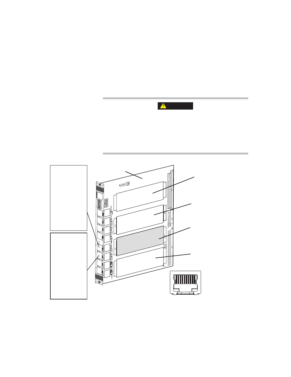
Model 494.46 8-Output D/A Card Pin Assignments
Analog output signals are typically routed from the D/A card through a
Model 494.76 8-Output BNC transition board. Signals are routed from the
D/A card through RJ-50 connectors located on the front of the I/O carrier
board.
The front-panel sockets on the I/O carrier board only accept cabling
with 10-pin, shielded, RJ-50 connectors.
The use of other RJ connector types (less than 10 pins or unshielded)
with the I/O carrier board can cause component damage.
Only use cables equipped with 10-pin, braided shielded, RJ-50 connectors
(with gray boot) with the I/O carrier board.
CAUTION
First
Pin 1 Not used
Pin 2 D/A Out [1]+
Pin 3 D/A Out [1] -
Pin 4 D/A Out [2]+
Pin 5 D/A Out [2] -
Pin 6 D/A Out [3]+
Pin 7 D/A Out [3] -
Pin 8 D/A Out [4]+
Pin 9 D/A Out [4] -
Pin 10 Reserved
1
2
3
4
5
6
7
8
Last
Pin 1 Not used
Pin 2 D/A Out [5]+
Pin 3 D/A Out [5] -
Pin 4 D/A Out [6]+
Pin 5 D/A Out [6] -
Pin 6 D/A Out [7]+
Pin 7 D/A Out [7] -
Pin 8 D/A Out [8]+
Pin 9 D/A Out [8] -
Pin 10 Reserved
RJ-50 Pin Assignments (front view)
1 2 3 4 5 6 7 8 9 10
J1A
J1B
J2A
J2B
J3A
J3B
J4A
J4B
494.46 8-Output D/A
Mezzanine Card
Card Slot 1
uses RJ-50 connectors
J1A and J1B
Card Slot 2
uses RJ-50 connectors
J2A and J2B
Card Slot 3
uses RJ-50 connectors
J3A and J3B
Card Slot 4
uses RJ-50 connectors
J4A and J4B
Model 494.40 I/O
Carrier Board