Model 494.40 i/o carrier board settings, Model 494.40 i/o carrier board settings 122 – MTS FlexTest Models 200 User Manual
Page 122
MTS FlexTest® Models 40/60/100/200 Controller Hardware
Model 494.40 I/O Carrier Board
VME Bus Boards
122
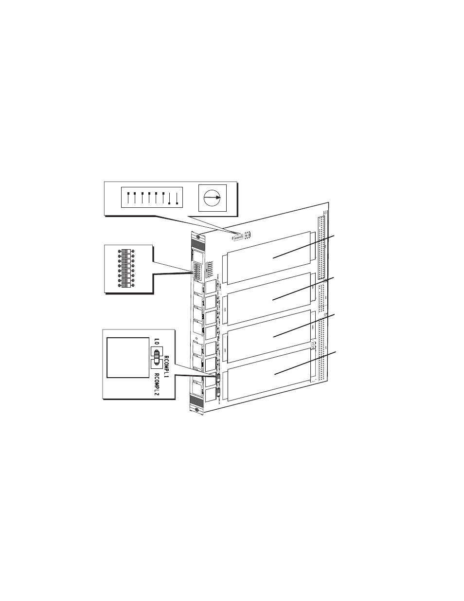
Model 494.40 I/O Carrier Board Settings
When you add or replace an I/O carrier board, you must set the board address. If
DUC cards are used, you can add optional shunt calibration and bridge-
completion resistors to the I/O carrier board. The locations for these settings are
shown below.
1
2
3
4
5
6
7
8
J1A
J1B
J2A
J2B
J3A
J3B
J4A
J4B
8 7 6 5 4 3 2 1
ON
B
0
1
2
3
4
5
6
7
8
9
A C E
D
F
J4A
1
2
3
4
5
6
7
8
J1A
J1B
J2A
J2B
J3A
J3B
J4A
J4B
Shunt Calibration
Resistors (front panel)
Address Setting
Bridge Completion
Resistors
Mezzanine
Card 1
Mezzanine
Card 2
Mezzanine
Card 3
Mezzanine
Card 4
This manual is related to the following products: