Fairbanks X SERIES PR 5410 Process Indicator User Manual
Page 13
Section 2: Process Indicator
10/08 13
51207 Revision 1
2.2 H
OUSING
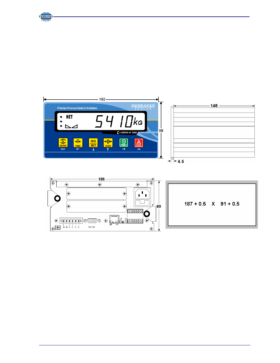
The instrument has aluminium housing and a front panel compliant with IP 65. It is suitable for
installation in a control cabinet. Keypad, display and display board form a unit with the front panel. A
square cut-out is required for installation. The cable connectors are on the back panel of the
housing. A 6-pin plug-in terminal block is provided for connection of the load cells. The built-in serial
interface has a 9-contact D-Sub female connector. Network connection is possible via the built-in
RJ-45 LAN socket. 3 Optocoupler inputs and 3 Optocoupler outputs can be connected using plug-in
terminals.
The cut-outs for up to 2 plug-in cards are covered by dummy plates.
The power cable plugs into the built-in power connector (with fuse socket).
Front view
Side view
View from the back
Panel cut-out