HEIDENHAIN iTNC 530 (60642x-04) User Manual
Page 538
538
Programming: Multiple Axis Machining
12.6 Thr
ee-dimensional t
o
ol compensation (sof
tw
ar
e option
2)
NC program
3-D ToolComp works only with programs that contain a surface normal
vector (see "Definition of a normalized vector" on page 529). The
following must be considered for NC program generation by means of
the CAM system:
If the NC program is calculated with reference to the center of the
sphere, you must define the nominal radius value R2 of the radius
cutter in the tool table (TOOL.T)
If the NC program is calculated with reference to the south pole of
the sphere, you must define the nominal radius value R2 of the
radius cutter and also the R2 value as a negative delta length in the
DL
column of the tool table (TOOL.T)
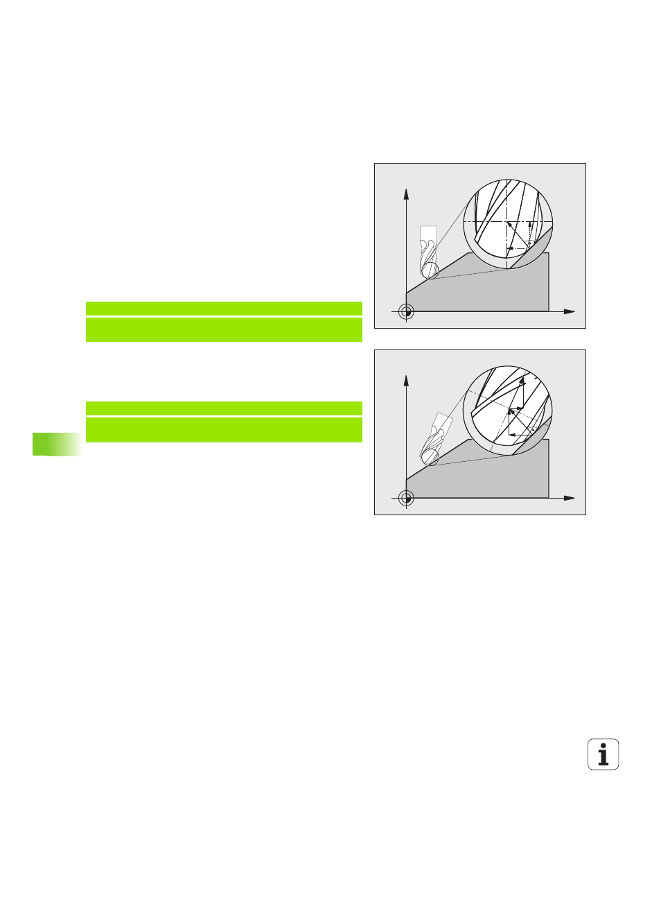
Example: Three-axis program with surface normal vector
Example: Five-axis program with surface normal vector
X
Z
NZ
NX
X
Z
NX
NZ
N
T
TZ
TX
FUNCTION TCPM OFF
LN X+31.737 Y+21.954 Z+33.165 NX+0.2637581 NY+0.0078922
NZ–0.8764339 F1000
X, Y, Z
:
Position of the leading tool point
NX, NY, NZ
: Components of the surface-normal vector
FUNCTION TCPM F TCP AXIS POS PATHCTRL AXIS
LN X+31.737 Y+21.954 Z+33.165 NX+0.2637581 NY+0.0078922
NZ–0.8764339 TX+0.0078922 TY–0.8764339 TZ+0.2590319 F1000
X, Y, Z
:
Position of the leading tool point
NX, NY, NZ
: Components of the surface-normal vector
TX, TY, TZ
: Components of the normalized vector for workpiece
orientation