Permissible tool shapes, Using other tools: delta values – HEIDENHAIN iTNC 530 (60642x-04) User Manual
Page 530
530
Programming: Multiple Axis Machining
12.6 Thr
ee-dimensional t
o
ol compensation (sof
tw
ar
e option
2)
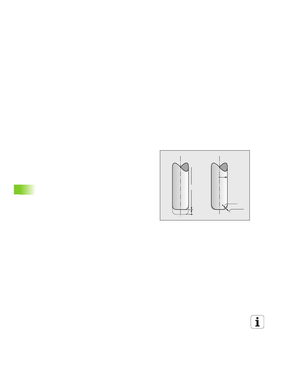
Permissible tool shapes
You can describe the permissible tool shapes in the tool table via tool
radii R and R2 (see figure):
Tool radius R: Distance from the tool center to the tool
circumference
Tool radius 2 R2: Radius of the curvature between tool tip and tool
circumference
The ratio of R to R2 determines the shape of the tool:
R2
= 0: End mill
R2
= R: Radius cutter
0 < R2 < R: Toroid cutter
These data also specify the coordinates of the tool datum P
T
.
Using other tools: Delta values
If you want to use tools that have different dimensions than the ones
you originally programmed, you can enter the difference between the
tool lengths and radii as delta values in the tool table or TOOL CALL:
Positive delta value DL, DR, DR2: The tool is larger than the original
tool (oversize).
Negative delta value DL, DR, DR2: The tool is smaller than the
original tool (undersize).
The TNC then compensates the tool position by the sum of the delta
values from the tool table and the tool call.
DL>0
L
R
DR2>0
R2