AJA FS2 User Manual
Page 198
200
•
All four GPI inputs are internally pulled high through a 10K ohm resistor
to an isolated +5V supply, so that a relay contact closure or any device
sinking at least 0.4 mA to ground will register a logic low.
•
All four GPI outputs are +5V TTL compatible, sourcing up to 6mA and
sinking up to 4mA each.
•
GPI Inputs light the front panel EXT LED when triggered.
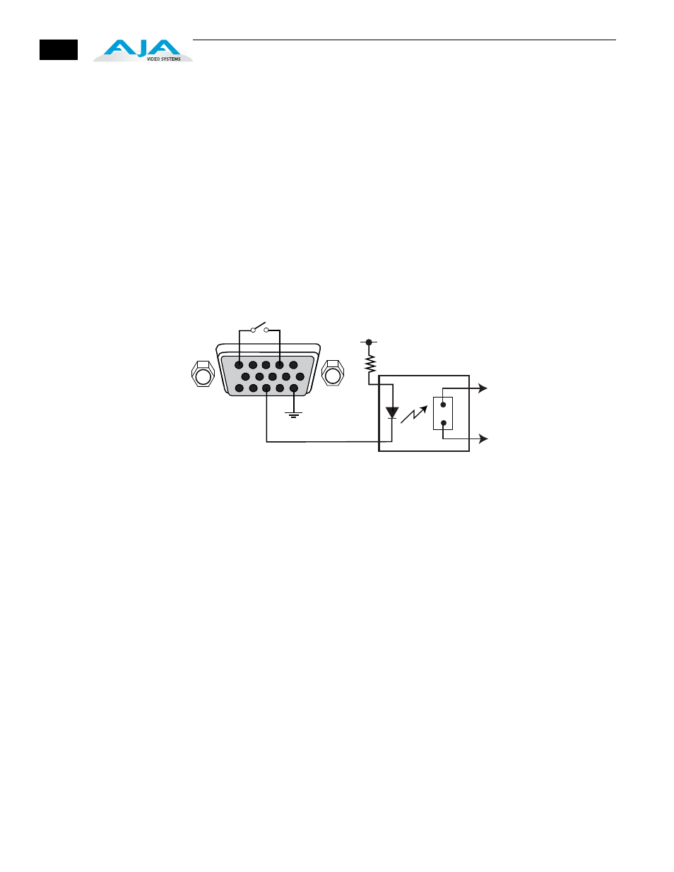
The following illustration shows typical external wiring to the GPI connector.
The GPI inputs require some kind of contact closure between the input pin
and the input ground pin to register the logic low that triggers the GPI input.
You can connect the outputs to TTL buffers that communicate the GPI output
logic levels to other devices. For example, you could use an opto-isolator
controlling a relay to activate other equipment as shown below.
Typical GPI Input and Output Connections
1
15
11
5
6
10
GPI Out 4
GPI
In 1
+V
xmit+
xmit-
Optical Relay (SSR)
To Tally Lamp etc.
GPI GND 4
GPI
GND 1