Operation – Rockwell Automation 20G PowerFlex 750-Series AC Drives User Manual
Page 43
Rockwell Automation Publication 750-RM002B-EN-P - September 2013
43
Drive Configuration
Chapter 1
Operation
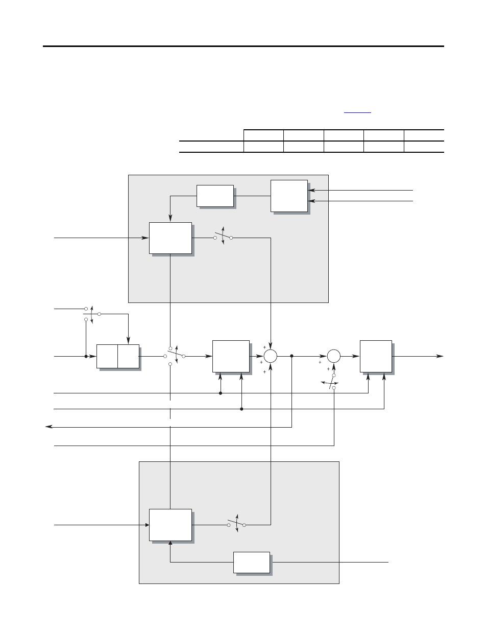
Bus voltage regulation begins when the bus voltage exceeds the bus voltage
regulation setpoint V
reg
and the switches shown in
move to the positions
shown.
Figure 1 - Bus Voltage Regulator, Current Limit, and Frequency Ramp
SW 1
SW 2
SW 3
SW 4
SW 5
Bus Regulation
Limit
Bus Reg
Open
Closed
Don’t Care
Current Limit
Derivative Gain
Block
Magnitude
Calculator
PI Gain Block
Current Limit Level
U Phase Motor Current
W Phase Motor Current
SW 3
I Limit,
No Bus Reg
Pr
opor
tional
Cha
nne
l
In
te
gr
al Ch
ann
el
0
Acc/Dec Rate
Jerk
Ramp
Jerk
Clamp
No Limit
SW 2
I Limit,
No Bus Reg
Bus Reg
Frequency
Ramp
(Integrator)
Output Frequency
Frequency
Limits
Frequency
Reference
SW 5
Speed
Control
Mode
Frequency Setpoint
Maximum Frequency, Minimum Speed, Maximum Speed, Overspeed Limit
Frequency Reference (to Ramp Control, Speed Ref, and so forth.)
Speed Control (Slip Comp, Process PI, and so forth.)
Bus Voltage Regulation Point, V
reg
Bus Voltage Regulator
Bus Voltage (V
bus
)
In
te
gr
al
C
hannel
Pr
op
or
tion
al
C
ha
nne
l
SW 4
Bus Reg On
Derivative
Gain Block
PI Gain Block
Limit
No Limit
SW 1