Auto restart, Configuration – Rockwell Automation 20G PowerFlex 750-Series AC Drives User Manual
Page 25
Rockwell Automation Publication 750-RM002B-EN-P - September 2013
25
Drive Configuration
Chapter 1
cause of this anomaly is the introduction of the jerk function. This bit needs to be
off during this condition.
When using single phase operation, connect the load to the U and V phases. The
W phase is energized but is not used.
Using a DC output can result in thermal issues. The drive may need to be
derated.
Investigate Possible Derating
Derate drive for sine wave filter.
Motor or drive overload is not affected by adjustable voltage mode.
Auto Restart
The Auto Restart feature provides the ability for the drive to automatically
perform a fault reset followed by a start attempt without user or application
intervention. Provided the drive has been programmed with a 2 wire control
scheme and the Run signal is maintained. This enables remote or unattended
operation. Only certain faults are allowed to be reset. Faults listed as Non-
Resettable in the programming manual indicate possible drive component
malfunction and are not resettable.
Use caution when enabling this feature, because the drive attempts to issue its
own start command based on user selected programming.
Configuration
Setting P348 [Auto Rstrt Tries] to a value greater than zero enables the Auto
Restart feature. Setting the number of tries equal to zero disables the feature.
M
O
TO
R C
O
N
TROL
Mt
r Ctr
l Opti
on
s
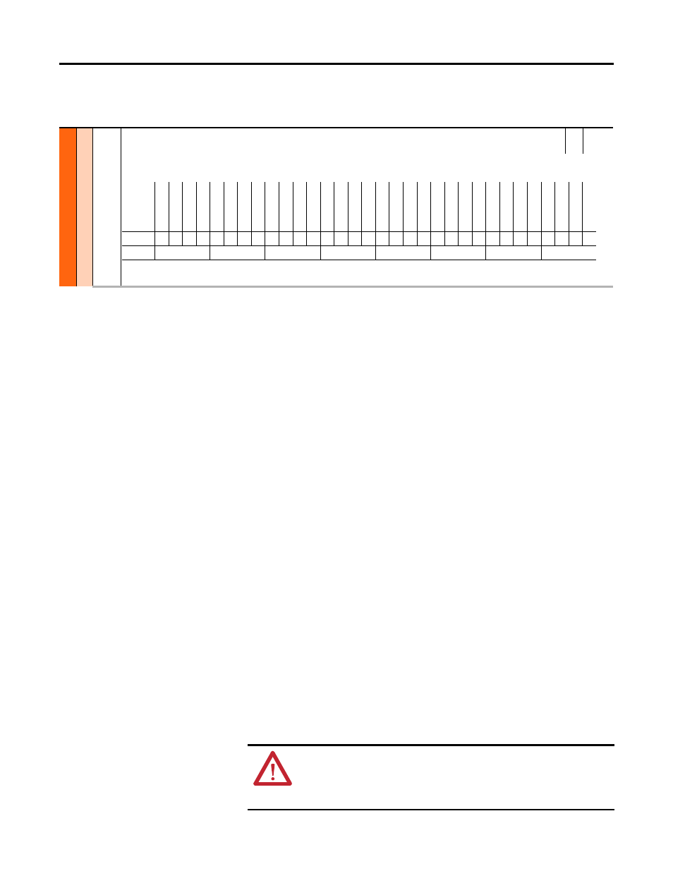
40
Mtr Options Cfg
Motor Options Configuration
RW 32-bit
Integer
Configuration of motor control-related functions. For motors above 200 Hz, a carrier frequency of 8 kHz or higher is recommended. Consider drive derate and motor
lead distance restrictions.
Options
Re
se
rv
ed
Re
se
rv
ed
Re
se
rv
ed
Re
se
rv
ed
Re
se
rv
ed
Re
se
rv
ed
Re
se
rv
ed
Re
se
rv
ed
Re
se
rv
ed
Re
se
rv
ed
Re
se
rv
ed
Re
se
rv
ed
Re
se
rv
ed
Re
se
rv
ed
Re
se
rv
ed
Re
se
rv
ed
Jerk Selec
t
No
t U
sed
Co
mmon Mode
Xsist
or D
iag
El
ec
t S
tab
DB W
hil
eS
to
p
PWM F
req
Lo
ck
As
yncPWML
ock
PWM T
ype
Sel
RS
A
daption
Re
flec
t W
av
e
Mtr L
ead
Rev
Enc
lsT
rq
Pr
ov
(1
)
(1) 755 drives only.
Tr
q Mo
de
Jo
g
Tr
q Mo
de
Sto
p
Ze
ro
T
rq
St
op
Default
0
0
0
0
0
0
0
0
0
0
0
0
0
0
0
0
0
0
0
1
1
0
0
0
1
1
1
0
0
1
1
1
Bit
32 30 29 28 27 26 25 24 23 22 21 20 19 18 17 16 15 14 13 12 11 10 9
8
7
6
5
4
3
2
1
0
ATTENTION: Equipment damage and/or personal injury may result if this
parameter is used in an inappropriate application. Do not use this function
without considering applicable local, national and international codes,
standards, regulations or industry guidelines.