Rockwell Automation 20G PowerFlex 750-Series AC Drives User Manual
Page 204
204
Rockwell Automation Publication 750-RM002B-EN-P - September 2013
Chapter 4
Motor Control
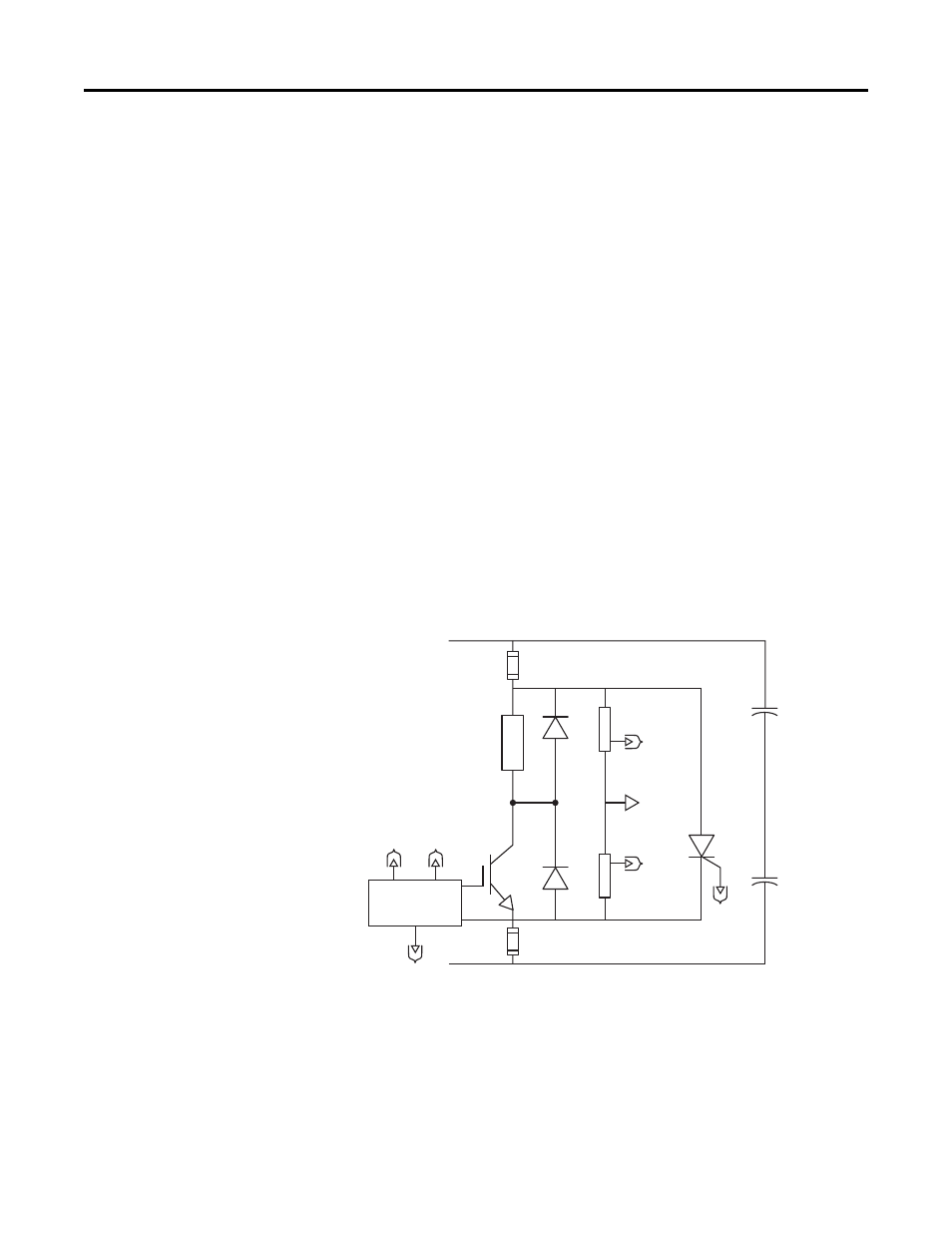
bus, and melting the fuse links. This action isolates the Chopper Module from
the DC bus until the problem can be resolved.
The Chopper Transistor is an Isolated Gate Bipolar Transistor (IGBT). There are
several transistor ratings that are used in the various Chopper Module ratings.
The most important rating is the collector current rating of the Chopper
Transistor that helps to determine the minimum Ohmic value used for the
Dynamic Brake Resistor. The Chopper Transistor is either ON or OFF,
connecting the Dynamic Brake Resistor to the DC bus and dissipating power, or
isolating the resistor from the DC bus.
The Chopper Transistor Voltage Control regulates the voltage of the DC bus
during regeneration. The average value of DC bus voltage is 375V DC (for 230V
AC input), 750V DC (for 460V AC input), and 937.5V DC (for 575V AC
input). The voltage dividers reduce the DC bus voltage to a low enough value
that is usable in signal circuit isolation and control. The DC bus feedback voltage
from the voltage dividers is compared to a reference voltage to actuate the
Chopper Transistor.
The Freewheel Diode (FWD) in parallel with the Dynamic Brake Resistor
enables any magnetic energy stored in the parasitic inductance of that circuit to
be safely dissipated during turn off of the Chopper Transistor.
Figure 22 - Chopper Module Schematic
Sizing the Dynamic Brake Module Gather the following information.
1.
The nameplate power rating of the motor in watts, kilowatts, or
horsepower.
2.
The nameplate speed rating of the motor in rpm or rps.
+DC Bus
-DC Bus
Fuse
Fuse
Dynamic
Brake
Resistor
Chopper Transistor
Voltage Control
To
Voltage
Divider
To
Crowbar
SCR Gate
Chopper
Transistor
Voltage
Divider
Signal
Common
Voltage
Divider
To Voltage
Control
To Voltage
Control
To
Voltage
Control
Crowbar
SCR
Bus Caps
Bus Caps
FWD
FWD