Rockwell Automation 20G PowerFlex 750-Series AC Drives User Manual
Page 211
Rockwell Automation Publication 750-RM002B-EN-P - September 2013
211
Motor Control
Chapter 4
Step 5 – Determine the Minimum Resistance
Each chopper module in the table above has a minimum resistance associated
with it. If a resistance lower than the value show in the table is connected to the
chopper module, the brake transistor is most likely be damaged.
Step 6 – Choosing the Dynamic Brake Resistance Value
To avoid damage to this transistor and get the desired braking performance, select
a resistor with a resistance between the maximum resistance calculated in Step 3
and the minimum resistance of the selected chopper module.
Step 7 – Estimating the Minimum Wattage requirements for the Dynamic
Brake Resistor
It is assumed that the application exhibits a periodic function of acceleration and
deceleration. If (t
3
- t
2
) = the time in seconds necessary for deceleration from
rated speed to 0 speed, and t
4
is the time in seconds before the process repeats
itself, then the average duty cycle is (t
3
- t
2
)/t
4
. The power as a function of time is
a linearly decreasing function from a value equal to the peak regenerative power
to 0 after (t
3
- t
2
) seconds have elapsed. The average power regenerated over the
interval of (t
3
- t
2
) seconds is Pb/2. The average power in watts regenerated over
the period t
4
is:
P
av
= average dynamic brake resistor dissipation, watts
t
3
- t
2
= Elapsed time to decelerate from rated speed to 0 speed, seconds
t
4
= Total cycle time or period of process, seconds
P
b
= Peak braking power, watts
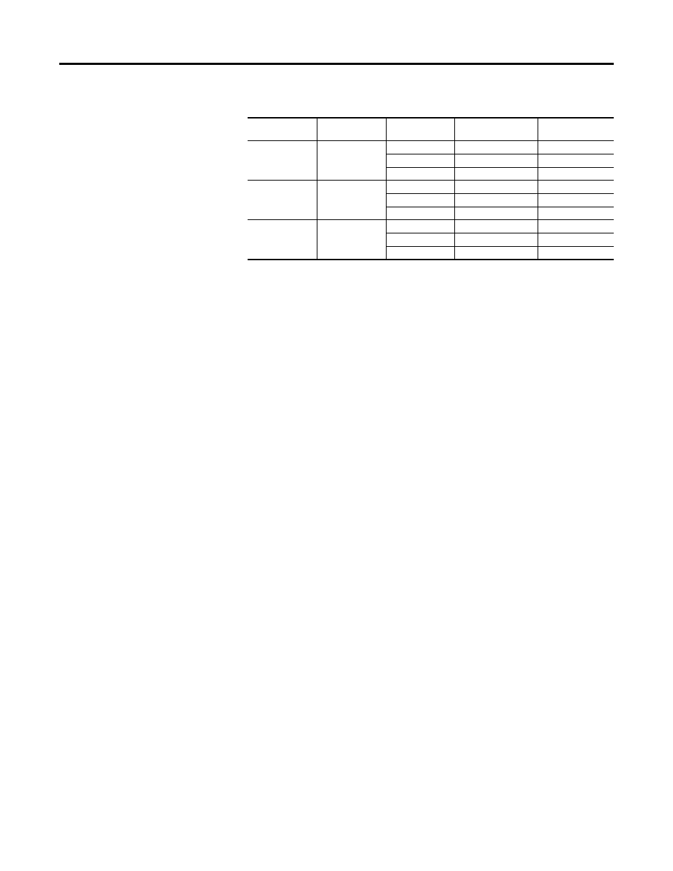
Drive Voltage
(Volts AC)
Turn-On Voltage
(Volts DC)
Cat. No.
Peak Transistor Current
Rating (Amps)
Minimum DB Resistor
Value (Ohms)
230
375
WA018
50
9.0
WA070
200
2.3
WA115
400
1.25
460
750
WB009
25
37
WB035
100
9.0
WB110
400
2.5
575
935
WC009
25
46
WC035
75
15.5
WC085
400
3.0
P
av
t
3
t
2
–
(
)
t
4
------------------
P
b
2
------
Ч
=