Ramp to hold – Rockwell Automation 20G PowerFlex 750-Series AC Drives User Manual
Page 100
100
Rockwell Automation Publication 750-RM002B-EN-P - September 2013
Chapter 1
Drive Configuration
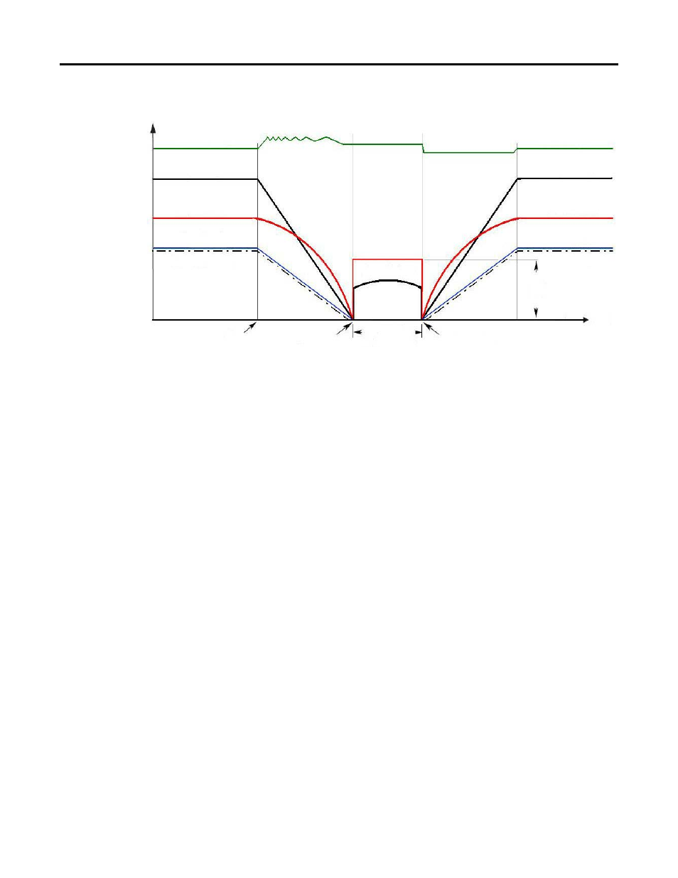
Ramp to Hold
This method combines two of the methods above. It uses drive output reduction
to stop the Load and DC injection to hold the load at zero speed once it has
stopped:
•
On Stop, drive output decreases according to the programmed pattern
from its present value to zero. The pattern can be linear or squared. The
output decreases to zero at the rate determined by the programmed P37
[Maximum Freq] and the programmed active P537/538 [Decel Time 1/2]
•
The reduction in output can be limited by other drive factors such as bus
or current regulation.
•
When the output reaches zero 3 phase drive output goes to zero (off ) and
the drive outputs DC voltage on the last used phase to provide the current
level programmed in P394 [DC Brake Level]. This voltage causes a
holding brake torque.
•
DC voltage to the motor continues until a Start command is reissued or
the drive is disabled.
•
If a Start command is reissued, DC Braking ceases and the drive returns to
normal AC operation. If an Enable command is removed, the drive enters a
Not Ready state until the enable is restored.
Bus Voltage
Output Voltage
Output Current
Motor Speed
Command Speed
Time
DC Hold for
indeterminate
amount of time.
Stop Command
Zero Command Speed
Output Voltage
Output Current
DC
Hold
Level
Bus Voltage
Output Voltage
Output Current
Motor Speed
Command Speed
Start Command