Auxiliary power supply option module (20-750-aps), Dual-port ethernet/ip option module (20-750-enetr), Regenerative/braking resistor – Rockwell Automation 20G PowerFlex 750-Series AC Drives User Manual
Page 347
Rockwell Automation Publication 750-RM002B-EN-P - September 2013
347
Integrated Motion on the EtherNet/IP Network Applications for PowerFlex 755 AC Drives
Chapter 6
Auxiliary Power Supply Option Module (20-750-APS)
Follow the same installation and configuration instructions provided in the
PowerFlex 750-Series AC Drives Installation Instructions, publication
Dual-Port EtherNet/IP Option Module (20-750-ENETR)
Follow the same installation and configuration instructions provided in the
PowerFlex 750-Series AC Drives Installation Instructions, publication
Regenerative/Braking
Resistor
When using a PowerFlex 755 drive with a dynamic brake (shunt regulator) in an
Integrated Motion on the Ethernet/IP network the dynamic brake must be set up
as part of the I/O connection of the PowerFlex 755 embedded Ethernet/IP
module (EENET-CM-
xx) properties. Failure to set up the dynamic brake
correctly could lead to mechanical damage of the machine. Dynamic brake
(shunt) resistor sizing is not covered in this document. For more information on
resistor sizing, see the Drives Engineering Handbook, publication
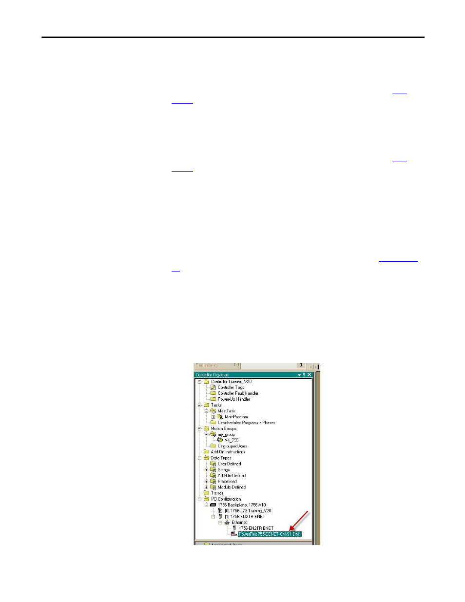
I/O Configuration for a Dynamic Brake (shunt regulator)
Follow these steps to configure a dynamic brake (shunt regulator) for a PowerFlex
755 drive in the Logix Designer application.
1.
In the I/O Configuration, double-click the PowerFlex 755-EENET-CM-
xx module and select Properties.
The Module Properties dialog box appears.