Carrier (pwm) frequency – Rockwell Automation 20G PowerFlex 750-Series AC Drives User Manual
Page 196
196
Rockwell Automation Publication 750-RM002B-EN-P - September 2013
Chapter 4
Motor Control
Carrier (PWM) Frequency
P38 [PWM Frequency] sets the carrier frequency at which the inverter output
IGBTs (Insulated Gate Bipolar Transistors) switch. In general, use the lowest
possible switching frequency that is acceptable for the particular application. An
increased carrier frequency causes less motor heating and lowers the audible noise
from the motor. However, it causes the IGBTs to heat up faster than by using the
factory default PWM frequency of 4 kHz or 2 kHz depending on drive’s the
frame size. The higher switching frequency smoothes the current waveform. This
reduces vibration in the motor windings and laminations reducing audible noise.
This is desirable in applications where motors are installed close to control rooms
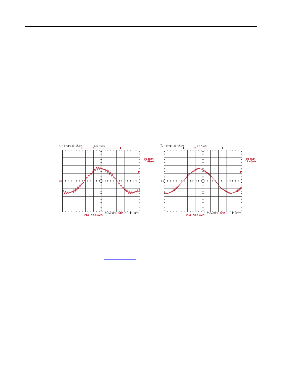
or in domestic environments. See
and note the output current at 2 kHz
and 4 kHz. The smoothing of the current waveform continues 12 kHz.
The maximum carrier frequency per frame size and the derating guidelines
according to PWM frequency can be found in the PowerFlex 750-Series AC
Drives Technical Data, publication
.
Figure 21 - Current at 2 kHz and 4 kHz PWM Frequency
Some undesirable effects of higher switching frequencies include higher cable
charging currents, higher potential for common mode noise and an increased risk
of motor winding insulation breakdown due to the reflected wave phenomenon.
Refer to the Wiring and Grounding Guidelines for PWM Drives, publication
for further information. A very large majority of all drive
applications will perform adequately at 2 kHz or 4 kHz.
Some applications require a fixed minimum PWM frequency (that is, using a sine
wave filter in the output of the drive). In this case, P40 [Mtr Options Cfg] Bit 9
“PWM FreqLock” should be set to prevent the drive from lowering its carrier
frequency due to a drive overload condition.
2 kHz
4 kHz