Rockwell Automation 20G PowerFlex 750-Series AC Drives User Manual
Page 109
Rockwell Automation Publication 750-RM002B-EN-P - September 2013
109
Feedback and I/O
Chapter 2
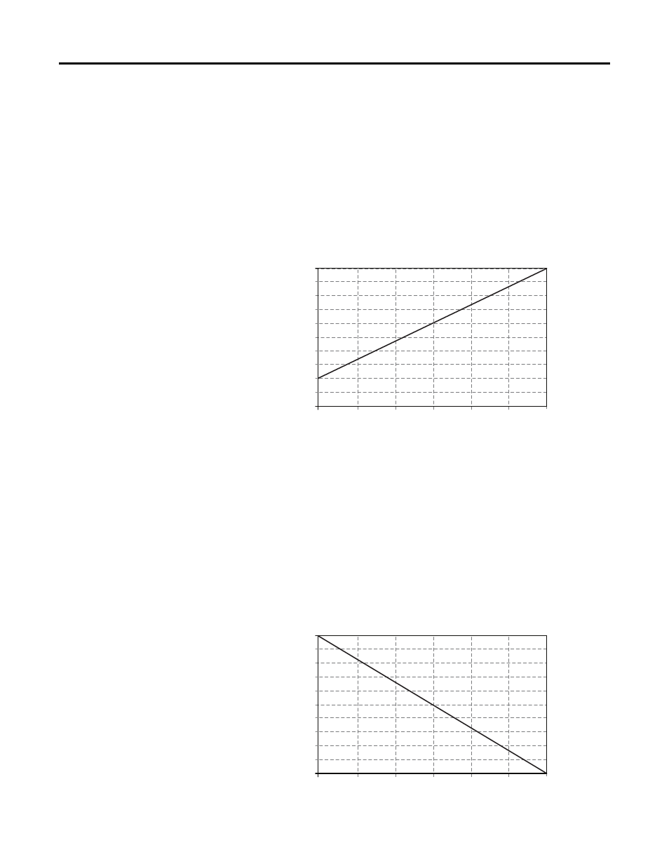
Example 4
•
P255 [Anlg In Type], Bit 0 = “1” (Current)
•
P545 [Spd Ref A Sel] = “Analog In 1”
•
P547 [Spd Ref A AnlgHi] = 60 Hz
•
P548 [Spd Ref A AnlgLo] = 0 Hz
•
P61 [Anlg In1 Hi] = 20 mA
•
P62 [Anlg In1 Lo] = 4 mA
This configuration is referred to as offset. In this case, a 4…20 mA input signal
provides 0…60 Hz output, providing a 4 mA offset in the speed command.
Example 5
•
P255 [Anlg In Type], Bit 0 = “0” (Voltage)
•
P545 [Spd Ref A Sel] = “Analog In 1”
•
P547 [Spd Ref A AnlgHi] = 0 Hz
•
P548 [Spd Ref A AnlgLo] = 60 Hz
•
P61 [Anlg In1 Hi] = 10V
•
P62 [Anlg In1 Lo] = 0V
This configuration is used to invert the operation of the input signal. Here,
maximum input (10V) represents 0 Hz and minimum input (0V) represents
60 Hz.
20
18
16
14
12
10
8
6
4
2
0
0 10 20 30 40 50 60
Output Hertz
Inp
ut mA
10
9
8
7
6
5
4
3
2
1
0
0 10 20 30 40 50 60
Output Hertz
In
pu
t V
ol
ts