Rockwell Automation 20G PowerFlex 750-Series AC Drives User Manual
Page 180
180
Rockwell Automation Publication 750-RM002B-EN-P - September 2013
Chapter 3
Diagnostics and Protection
Figure 18 - PWM Voltage at the Drive Output Terminals
Ideally, the voltage waveform at the motor looks exactly the same as the output of
the drive. However, the voltage at the motor has individual on/off pulses that
make up the PWM voltage waveform along with a ringing that occurs at every
switching transition. This is shown in
. The peaks of the ringing
waveform can easily reach two times the peak of the voltage pulses at the drive
(the DC bus voltage). After a short time, the ringing dies away and the motor sees
the normal DC bus voltage level. It is this peak level of the ringing voltage that
causes motor failure.
Figure 19 - PWM Voltage at the Motor Terminals
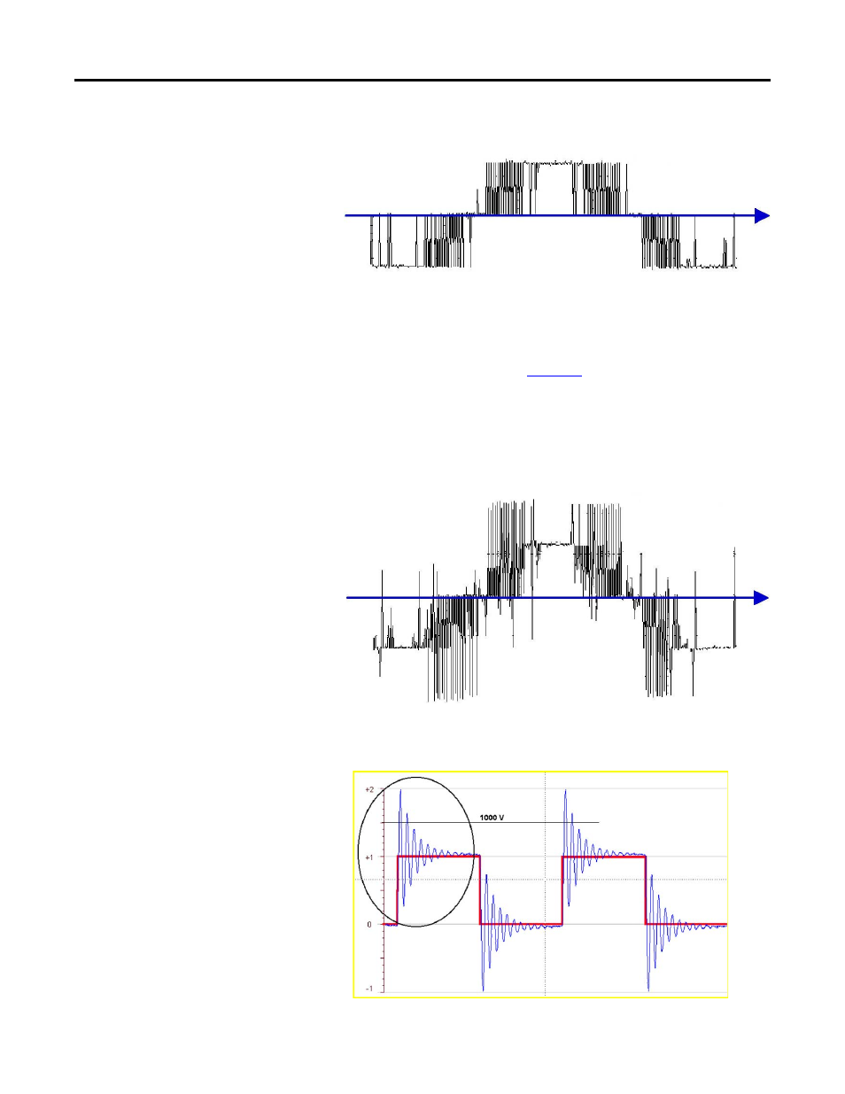
Shorten the time sweep or magnify these pulses and the ringing effect at the
motor terminals can be seen.
DC Bus Volts
0 Volts
2X to 4X Voltage Spike
0 Volts