Configuration – Rockwell Automation 20G PowerFlex 750-Series AC Drives User Manual
Page 131
Rockwell Automation Publication 750-RM002B-EN-P - September 2013
131
Feedback and I/O
Chapter 2
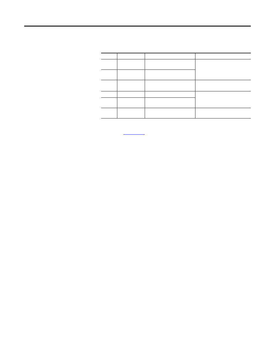
Catalog number 20-750-2263C-1R2T provides one transistor output and two
relay outputs on TB2 at the front of option module.
Refer to the PowerFlex 750-Series AC Drives Installation Instructions,
publicatio
, for PowerFlex 750-Series Option Module I/O wiring
examples.
Configuration
Each digital output can be programmed to change state based on one of many
different conditions. These conditions can fall into different categories.
•
Drive status conditions (fault, alarm, and reverse).
•
Level conditions (DC bus voltage, current, and frequency)
•
Controlled by a digital input.
•
Controlled by the network.
•
Controlled by DeviceLogix software.
Terminal
Name
Description
Rating
R0NC
Relay 0 N.C.
Output Relay 0 normally closed
contact
240V AC, 24V DC, 2A max
Resistive Only
R0C
Relay 0 Common
Output
Relay 0 common
R0NO
Relay 0 N.O.
Output Relay 0 normally open contact 240V AC, 24V DC, 2A max
General Purpose (Inductive) / Resistive
T0
Transistor Output 0 Transistor Output
24VDC = 1A max
24VDC = 0.4 Max for U.L. applications.
Resistive
TC Transistor
Output
Common
Transistor Output Common
T1
Transistor Output 1 Transistor Output
24VDC = 1A max 24VDC = 0.4 Max for
U.L. applications. Resistive