Controlled by network – Rockwell Automation 20G PowerFlex 750-Series AC Drives User Manual
Page 142
142
Rockwell Automation Publication 750-RM002B-EN-P - September 2013
Chapter 2
Feedback and I/O
Controlled by Network
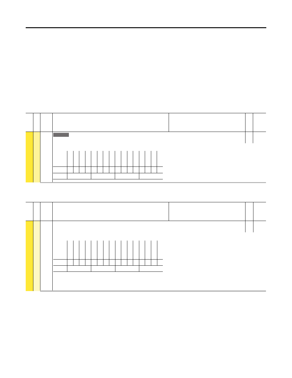
This configuration is used when it is desired to control the digital outputs over
network communication instead of a drive related function. In the case for the
PowerFlex 753 embedded digital outputs, P227 [Dig Out Setpoint] is utilized
and in the case for the PowerFlex 750-Series Option Module, P7 [Dig Out
Setpoint] is utilized. To complete the configuration for control over a network, a
datalink must be configured for the respective Digital Output Setpoint
parameter.
Related PowerFlex 753 Setpoint parameter information noted below.
Depending on the PowerFlex 750-Series Option Module(s) installed in the drive,
related Setpoint parameter information noted below.
Fil
e
Gro
u
p
No.
Display Name
Full Name
Description
Values
Read-W
ri
te
Da
ta
T
yp
e
FEEDBA
CK & I/O
D
igi
tal O
utput
s
227
Dig Out Setpoint
Digital Output Setpoint
RO
16-bit
Integer
Controls Relay or Transistor Outputs when chosen as the source. Can be used to control outputs from a communication device using DataLinks.
753
Options
Re
se
rv
ed
Re
se
rv
ed
Re
se
rv
ed
Re
se
rv
ed
Re
se
rv
ed
Re
se
rv
ed
Re
se
rv
ed
Re
se
rv
ed
Re
se
rv
ed
Re
se
rv
ed
Re
se
rv
ed
Re
se
rv
ed
Re
se
rv
ed
Re
se
rv
ed
Tr
an
s O
ut
0
Re
la
y Out
0
Default
0
0
0
0
0
0
0
0
0
0
0
0
0
0
0
0
Bit
15 14 13 12 11 10 9
8
7
6
5
4
3
2
1
0
0 = Condition False
1 = Condition True
Fil
e
Gr
oup
No.
Display Name
Full Name
Description
Values
Re
ad
-Write
Da
ta
T
yp
e
I/O
D
igi
ta
l O
u
tpu
ts
7
Dig Out Setpoint
Digital Output Setpoint
RW 16-bit
Integer
Controls Relay or Transistor Outputs when chosen as the source. Can be used to control outputs from a communication device using DataLinks.
(1) Bit 1 = “Trans Out 0” for I/O Module model 20-750-2263C-1R2T
= “Relay Out 1” for I/O Module models 20-750-2262C-2R and 20-750-2262D-2R
(2) Bit 2 is only used by I/O Module 20-750-2263C-1R2T
Options
Re
ser
ved
Re
ser
ved
Re
ser
ved
Re
ser
ved
Re
ser
ved
Re
ser
ved
Re
ser
ved
Re
ser
ved
Re
ser
ved
Re
ser
ved
Re
ser
ved
Re
ser
ved
Re
ser
ved
Tr
an
s O
ut
1
(2
)
Tr
an
s O
ut
0
(1
)
Re
la
y O
ut
0
Default
0
0
0
0
0
0
0
0
0
0
0
0
0
0
0
0
Bit
15 14 13 12 11 10 9
8
7
6
5
4
3
2
1
0
0 = Output De-energized
1 = Output Energized