Configuration with optional i/o board – Rockwell Automation 20G PowerFlex 750-Series AC Drives User Manual
Page 153
Rockwell Automation Publication 750-RM002B-EN-P - September 2013
153
Feedback and I/O
Chapter 2
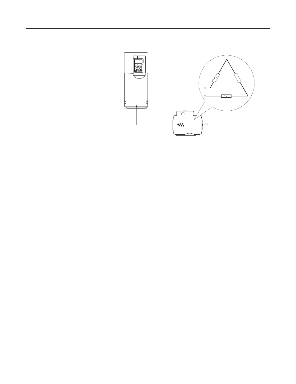
Figure 14 - PTC Connection
Configuration with PTC connected to PowerFlex 753 Main Control
Board
Port 0: P250 [PTC Cfg] = 0 “Ignore,” 1 “Alarm,” 2 “Flt Minor,” 3 “FltCoastStop,”
4 “Flt RampStop,” or 5 “Flt CL Stop”
Status is shown in Port 0: P251 [PTC Sts]
Configuration with Optional I/O Board
Port X (I/O Module): P40 [PTC Cfg] = 0 “Ignore,” 1 “Alarm,” 2 “Flt Minor,” 3
“Flt CoastStop,” 4 “Flt RampStop,” or 5 “Flt CL Stop”
Status is shown in Port X (I/O Module): P41 [PTC Sts] and Port X (I/O
Module): P42 [PTC Raw Value]
Configuration with 11-Series I/O module fitted with ATEX Option
Status is shown in Port X (I/O Module): P41 [ATEX Sts] The fault action is not
configurable when the ATEX module is used.