Rockwell Automation 20G PowerFlex 750-Series AC Drives User Manual
Page 147
Rockwell Automation Publication 750-RM002B-EN-P - September 2013
147
Feedback and I/O
Chapter 2
PowerFlex 753 Invert parameter information noted below.
Depending on the PowerFlex 750-Series Option Module(s) installed, Invert
parameter information noted below.
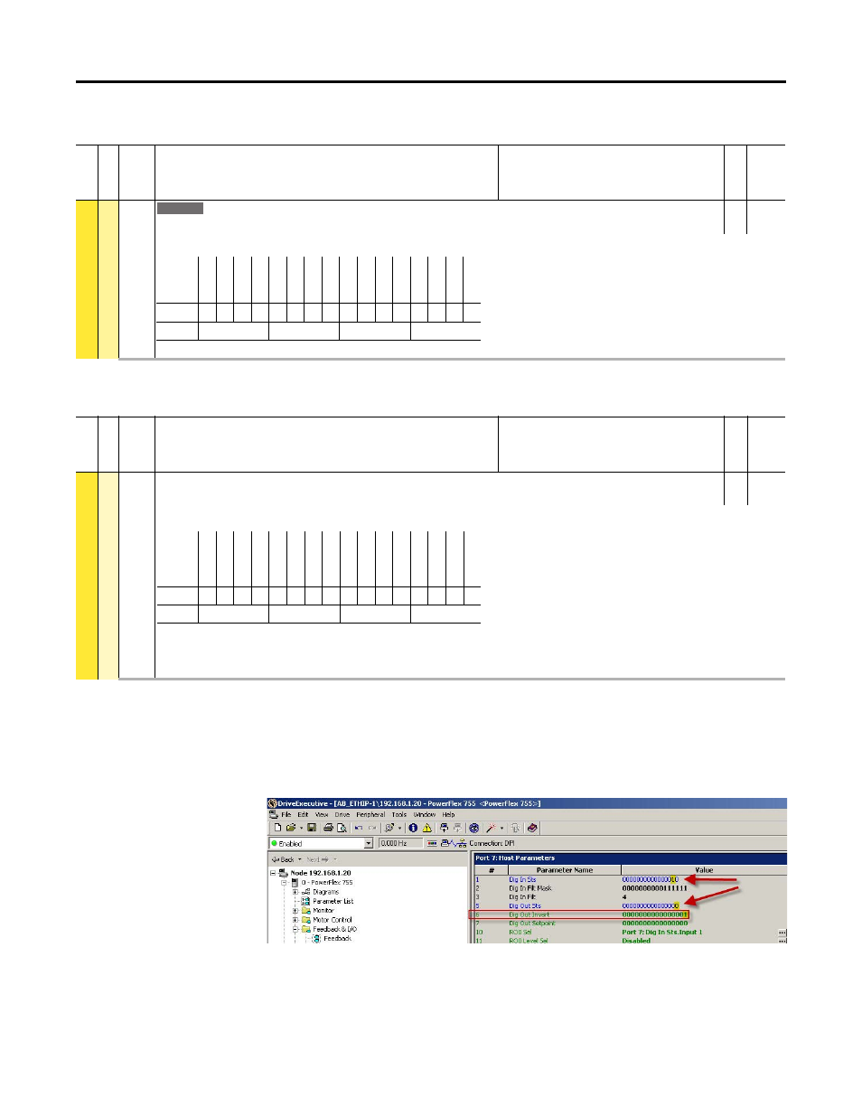
Example
In this example, the drive is utilizing a 24VDC, two relay Option Module in Port
7 with P10 [RO0 Sel] is programmed for Port 7: Dig In Sts.Input 1. Notice below
when the Invert bit for Relay Out 0, when the input status is true (1), the digital
output status bit is false (0).
Fil
e
Gr
ou
p
No.
Display Name
Full Name
Description
Values
Re
ad
-Write
Da
ta T
ype
FEEDBA
CK & I/O
Digi
tal O
utpu
ts
226
Dig Out Invert
Digital Output Invert
RO
16-bit
Integer
Inverts the selected digital output.
753
Options
Re
ser
ve
d
Re
ser
ve
d
Re
ser
ve
d
Re
ser
ve
d
Re
ser
ve
d
Re
ser
ve
d
Re
ser
ve
d
Re
ser
ve
d
Re
ser
ve
d
Re
ser
ve
d
Re
ser
ve
d
Re
ser
ve
d
Re
ser
ve
d
Re
ser
ve
d
Tr
an
s O
ut
0
Re
la
y O
ut 0
Default
0
0
0
0
0
0
0
0
0
0
0
0
0
0
0
0
Bit
15 14 13 12 11 10 9
8
7
6
5
4
3
2
1
0
0 = Condition False
1 = Condition True
Fi
le
Grou
p
No.
Display Name
Full Name
Description
Values
Re
ad
-W
ri
te
Da
ta
T
ype
I/O
Digi
tal O
utpu
ts
6
Dig Out Invert
Digital Output Invert
RW 16-bit
Integer
Inverts the selected digital output.
(1) Bit 1 = “Trans Out 0” for I/O Module model 20-750-2263C-1R2T.
= “Relay Out 1” for I/O Module models 20-750-2262C-2R and 20-750-2262D-2R.
(2) Bit 2 is used only by I/O Module 20-750-2263C-1R2T.
Options
Rese
rv
ed
Rese
rv
ed
Rese
rv
ed
Rese
rv
ed
Rese
rv
ed
Rese
rv
ed
Rese
rv
ed
Rese
rv
ed
Rese
rv
ed
Rese
rv
ed
Rese
rv
ed
Rese
rv
ed
Rese
rv
ed
Tr
an
s O
ut
1
(2)
Tr
an
s O
ut
0
(1)
Rela
y O
ut
0
Default
0
0
0
0
0
0
0
0
0
0
0
0
0
0
0
0
Bit
15 14 13 12 11 10 9
8
7
6
5
4
3
2
1
0
0 = Output Not Inverted
1 = Output Inverted