Rockwell Automation 20P PowerFlex Digital DC Drive User Manual
Page 81
Rockwell Automation Publication 20P-UM001I-EN-P - February 2013
81
Installation and Wiring
Chapter 1
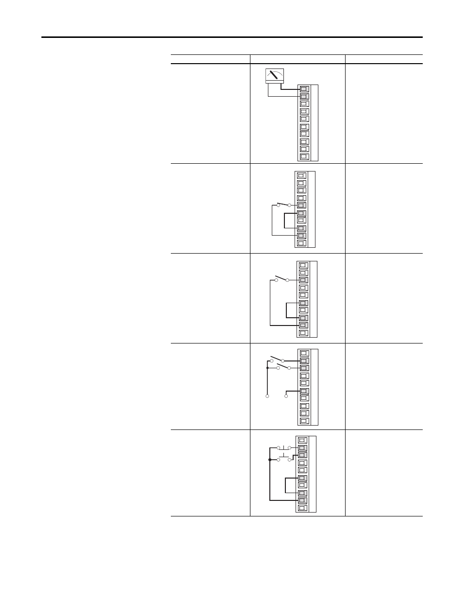
Analog Output Bipolar Signal
±
10V Bipolar (based on the signal of
the assigned input source - for
example Analog Input 1)
or
0…10V Unipolar (shown)
• Select Source Value:
66 [Anlg Out1 Sel]
• Adjust Scaling:
62 [Anlg Out1 Scale]
Enable Input
24V DC internal supply
• No Changes Required.
Note: If the digital input used for
“Enable” is changed from the
default setting of digital input 4,
the wiring must be changed
accordingly.
2-Wire Control Non-Reversing
24V DC internal supply
Important: Programming inputs
for 2-wire control deactivates the
HIM Start and Jog buttons.
• Disable Digital Input 1:
133 [Digital In1 Sel]
= 0 “Not Used”
• Set Digital Input 2:
134 [Digital In2 Sel]
= 5 “Run”
2-Wire Control
Reversing
24V DC external supply
Important: Programming inputs
for 2-wire control deactivates the
HIM Start and Jog buttons.
• Set Digital Input 1:
133 [Digital In1 Sel]
= 6 “Run Forward”
• Set Digital Input 2:
134 [Digital In2 Sel]
= 7 “Run Reverse”
3-Wire Control
24V DC internal supply
• No Changes Required.
Input/Output
Connection Example
Required Parameter Changes
21
22
23
24
25
26
27
28
29
30
+
–
11
12
13
14
15
16
17
18
19
20
11
12
13
14
15
16
17
18
19
20
Stop-Run
Run Rev.
Run Fwd.
+24V
Neutral/
Common
11
12
13
14
15
16
17
18
19
20
11
12
13
14
15
16
17
18
19
20
Stop
Start