Analog input configuration, Example 1, Example 2 – Rockwell Automation 20P PowerFlex Digital DC Drive User Manual
Page 262: Example 1: example 2, Analog input configuration on
262
Rockwell Automation Publication 20P-UM001I-EN-P - February 2013
Appendix C
Application Notes
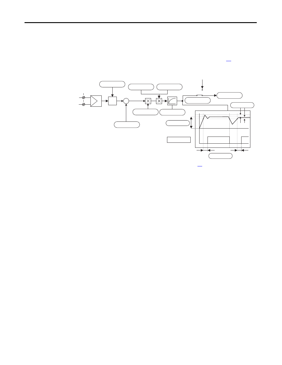
Analog Input Configuration
The analog inputs default to ±10V. To configure the analog inputs for 0-10V, set
parameters [Anlg Inx Config] to 1, “0-10V”. To configure the analog inputs for a
current signal, set parameters [Anlg Inx Config] to 2, “0 - 20mA” or 3, “4 to
20mA”. In addition, switches S9, S10 and S11 must be properly configured (see
Control Circuit Board Jumper and DIP Switch Settings on page
for more
information).
Example 1:
The speed reference value of a drive is defined with an external voltage of 5V.
With this value the drive should reach the maximum allowable speed set in Par
45 [Max Ref Speed]. Enter a scaling factor of 2 in [Anlg Inx Scale] to scale the
input voltage from 5V to 10V.
Example 2:
An external analog reference reaches a maximum value of 9.8V. Enter a scaling
factor of 1.020 in [Anlg Inx Scale] to scale the maximum voltage from 9.8V to
10V.
The same result could be obtained via parameter [Anlgx Tune Scale], by entering
the values of the appropriate parameters via the HIM. The maximum possible
analog value (in this case 9.8V) would have to be present at the terminal with a
positive polarity.
Σ
+
-
2
1
Volts
Ref_1-
Ref_1+
HW
input
type
Window comparator
F
From Digital Reference Setting
Anlg In1 Cmp
0
0 ms
Anlg In1 Cmp Eq
Anlg In1 Cmp Dly
Anlg In1 Cmp Er
0
+/-10V
Anlg In1 Config
1
Ain1 Tune Scale
0
Anlg In1 Offset
1
Anlg In1 Scale
0
Anlg In1 Tune
0 ms
Anlg In 1 Filter
0
Anlg In1 Target
Speed Ref A
Anlg In1 Sel
Analog Input 1
See the “Analog Inputs / Outputs & Mapping” block diagram on page
for more information.