Po we rf le x dc drive, Figure 20 - power wiring with dc output contactor – Rockwell Automation 20P PowerFlex Digital DC Drive User Manual
Page 48
48
Rockwell Automation Publication 20P-UM001I-EN-P - February 2013
Chapter 1
Installation and Wiring
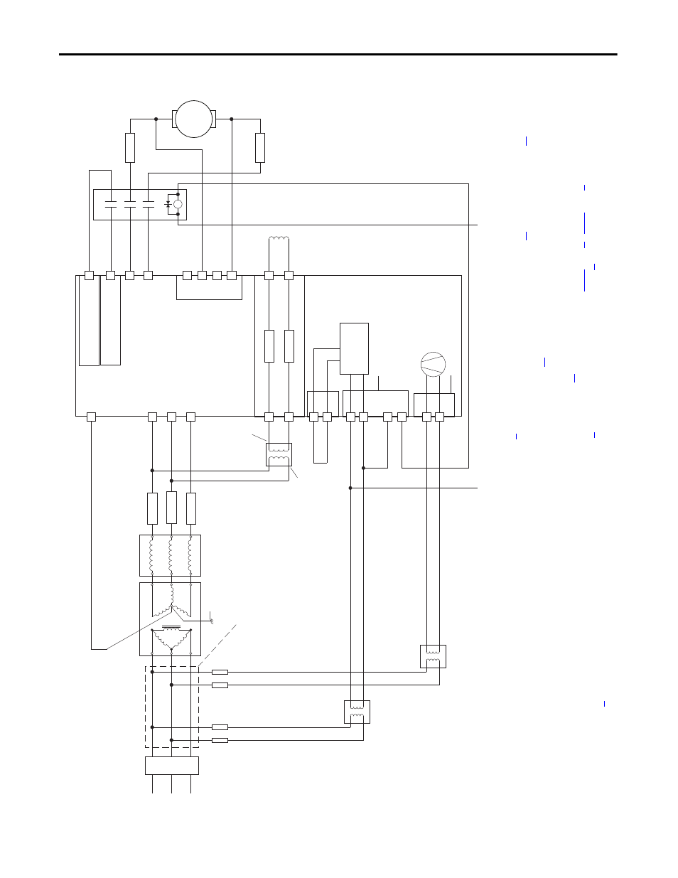
Figure 20 - Power Wiring with DC Output Contactor
C
D
Po
we
rF
le
x DC
Drive
36
(7)
34
(4)
(on I/O TB4)
19
(5)
(+2
4V on I/O TB2)
Co
nt
ro
l
Boar
d P
/S
115V
or
230V
(1)
V2
U2
F2
35
(7)
U
V
W
3 P
has
e
AC lin
e
L1
L2
L3
U1
V1
C1
D1
F1
FS1
(3)
FS1
(3)
FS1
(3)
FU1
FV1
FU
FU
Field Power Terminal Block
Control Power / Relay Outputs
Terminal Block
A1
A2
Armature Volt.
Fdbk. Term.
1A1
1A2
U3
V3
Fan Power Terminal Block
(8)
230V
FU
FU
Line Reactor
(2)
Lockable
Installation
Disconnect
SB
(1)
SA
(1)
M
Aux
(N
.O
. R
ela
y)
M1 DC
Co
nt
ac
to
r
A1
A2
13
14
L1
L2
A1
T1
T2
A2
FS2
(6)
FS2
(6)
These connections
must be taken from
the primary side of
the Isolation Transformer
or Line Reactor
(clean power).
AC Input
Voltage
AC Input
Voltage
Isolation
Transformer
(2)
Safety Ground
PE
AC Input
Voltage
460 VAC
Max. or
230 VAC
Min.
(9)
(1
) For f
rame B and
C
dri
ves
o
nly, a
jumper
is
req
uired b
et
w
een terminals
SA
and SB
fo
r 115V AC
contro
l i
np
ut po
wer.
S
ee Co
o
n
pa
ge
fo
r more inf
ormat
io
n.
(2
) A
n Is
ol
at
io
n T
ra
ns
fo
rmer a
nd/
or
3
…
5%
imp
eda
nce
Line
R
eac
to
r is
re
qui
red.
If
th
e Is
ol
at
io
n Tra
nsf
or
mer p
rov
id
es
th
e req
ui
red
3…
5%
im
pe
dan
ce,
a
Line
R
eact
or is
no
t req
uire
d.
See
ge
and
o
n p
ag
e
fo
r
recommen
da
tions.
(3)
A
C i
npu
t fu
se
s
fo
r the a
rmature
co
nverter a
re cu
sto
m
er su
ppl
ied
fo
r fram
e A
a
nd B
d
rive
s and
are
interna
lly
mo
unted
o
n f
ram
e C
a
nd D d
riv
es
. S
ee Dr
on
p
ag
for
fu
se
recomme
nda
tion
s.
(4
) Pa
r 1
40
[D
ig
ital
In8
Sel]
se
t to
3
1 “
Cont
ac
to
r”
(5
) If
us
in
g t
he
+2
4V
in
te
rnal
po
w
er s
up
ply
, te
rmina
l 1
8 (
24V
co
mmo
n)
mus
t be
jump
ered
to
te
rm
ina
l 3
5 (
di
git
al i
npu
t com
m
on
).
(6)
Cu
sto
mer sup
pl
ied
arm
ature o
utp
ut f
use
s
are
requ
ired
o
n f
ou
r qu
adra
nt
and
a
re re
co
mm
ende
d o
n
tw
o q
uad
rant
Fra
m
e
A a
nd
B
dri
ve
s.
See Dri
n p
ag
fo
r fu
se
rec
omme
nda
tions.
(7) P
ar 139
1
[C
on
tac
torC
ontro
l] = 3 “DC
Cntctr
”
an
d
Pa
r 139
2 [
Relay
Out
1
Sel]
= 25
“
Co
nt
acto
r”.
Import
ant:
Terminal 35 and 36 ar
e on the
Co
ntr
ol
Po
wer / Relay Out
puts Termi
nal
bl
ock
, NOT
th
e I/O te
rmina
l b
lo
cks. See
Fi
gu
re
35
on pag
e
63
…
on pa
ge
.
(8
) Fram
e C
& D
d
riv
es
o
nly
re
qu
ire a
n e
xt
erna
l p
ow
er
su
pp
ly f
or
th
e
he
atsi
nk cooli
ng fa
n. See
pa
ge
a
nd
on
p
ag
fo
r more inf
ormat
io
n.
(9)
See Fie
on
pa
ge
.