Figure 19, Po w er fl ex d c drive, Figure 19 - power wiring with ac input contactor – Rockwell Automation 20P PowerFlex Digital DC Drive User Manual
Page 47
Rockwell Automation Publication 20P-UM001I-EN-P - February 2013
47
Installation and Wiring
Chapter 1
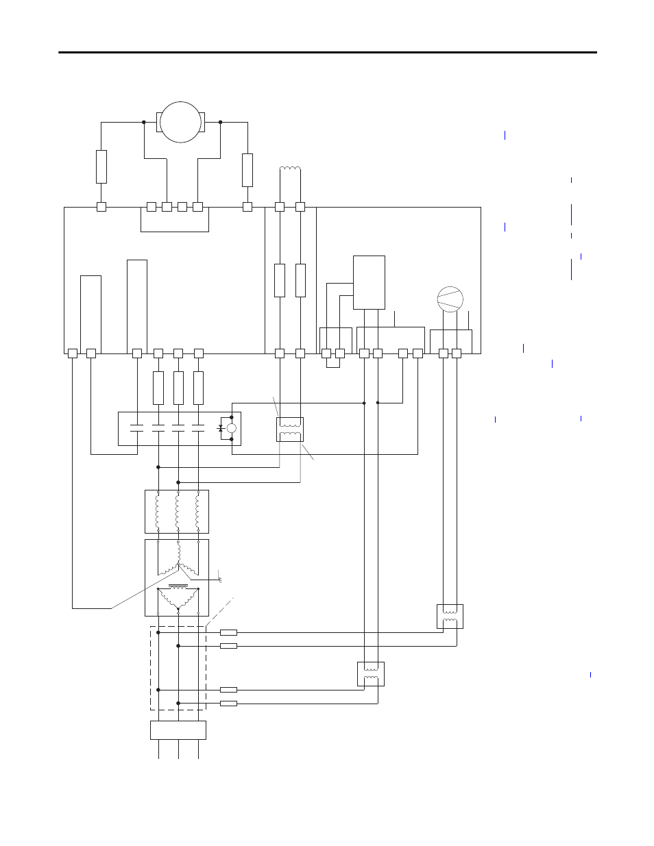
Figure 19 - Power Wiring with AC Input Contactor
M
C
D
Aux
Po
w
er
Fl
ex
D
C
Drive
36
(8)
34
(4)
(on I/O TB4)
19
(5)
(+2
4V on I/O TB2)
(N
.O
. R
el
ay)
M1 AC Contactor
Co
nt
ro
l
Bo
ar
d P/
S
AC Input
Voltage
115V
or
230V
(1)
V2
U2
F2
A1
A2
35
(8)
U
V
W
3 P
has
e
AC lin
e
L1
L2
L3
13
14
L1
L2
L3
A1
T1
T2
T3
A2
U1
V1
C1
D1
F1
FS2
(6)
FS2
(6)
FS1
(3)
FS1
(3)
FS1
(3)
FU1
FV1
FU
FU
Field Power Terminal Block
Control Power / Relay Outputs
Terminal Block
A1
A2
Armature Volt.
Fdbk. Term.
(7)
1A1
1A2
U3
V3
Fan Power Terminal Block
(9)
230V
FU
FU
Line Reactor
(2)
Isolation
Transformer
(2)
Lockable
Installation
Disconnect
SB
(1)
SA
(1)
These connections
must be taken from
the primary side of
the Isolation Transformer
or Line Reactor
(clean power).
AC Input
Voltage
PE
Safety Ground
AC Input
Voltage
460 VAC
Max. or
230 VAC
Min.
(10)
(1)
F
or frame B
and C
d
riv
es only,
a jum
per
is
requi
red
between
te
rmi
nals SA an
d SB
fo
r 115V AC
cont
rol input p
ower. See C
o
n p
ag
fo
r m
ore
infor
m
ation.
(2
) An I
sola
tio
n
Transforme
r and
/or 3…
5% im
ped
anc
e Li
ne Rea
ctor
is
requ
ired
. If
the Iso
lati
on
Tr
ansf
orme
r pro
vi
des
the requ
ired
3…
5%
im
pe
da
nc
e,
a L
in
e Re
ac
to
r is
n
ot
req
uire
d.
Se
e AC
s on
pa
ge
an
d I
o
n p
ag
for
rec
omm
endations.
(3
) A
C
inp
ut f
uses f
or the
arma
tu
re co
nv
erte
r are
custom
er supp
lied
fo
r f
ra
m
e
A
and
B
driv
es a
nd a
re i
nternal
ly m
ou
nted
on
fram
e C
an
d D d
riv
es. S
ee Dri
n o
n p
age
fo
r fuse re
co
m
m
endations.
(4)
Par 140 [Di
gital In8 Se
l] set to 31 “C
ontacto
r”
(5
) I
f u
si
ng
th
e +
24
V
int
erna
l p
ow
er
su
pp
ly,
te
rmi
nal
18
(2
4V
co
mmo
n)
mu
st
b
e ju
mpere
d t
o t
ermi
nal
35
(d
igi
tal
inp
ut
co
mmo
n).
(6)
Cu
sto
m
er
su
pp
lied
a
rm
atu
re
ou
tp
ut
fu
se
s a
re req
ui
re
d o
n
fo
ur q
uad
rant
a
nd
are
re
co
mmend
ed
o
n t
w
o
qua
dra
nt
Frame
A
an
d B
dri
ve
s.
See
on
pa
ge
for f
us
e recomme
ndat
io
ns
.
(7
) Op
tio
nal
arma
tu
re
vo
ltag
e f
ee
db
ack
se
nsi
ng
no
t re
qu
ired
wit
h A
C co
nt
act
or.
(8)
Par 1391 [C
ont
acto
rCo
ntrol]
= 1
“A
C
Cn
tctr” an
d Par 1392 [
Relay
Ou
t 1 Se
l] = 25 “C
ontactor
”.
Impor
tant
: T
er
m
in
al
35 an
d
36
a
re
on
th
e C
on
tro
l P
owe
r / Re
la
y
Ou
tputs Te
rm
ina
l b
lo
ck, NOT th
e I
/O
te
rm
in
al
b
loc
ks
. S
ee
Fi
gu
re
35
on
pa
ge
63
…
on pa
ge
.
(9
) F
ra
m
e
C &
D dri
ves o
nly
req
uire
an
ex
te
rnal
po
wer sup
ply
fo
r the
hea
tsin
k cool
ing
fan. See
ge
and
o
n p
ag
e
fo
r mo
re
infor
m
ation.
(1
0)
Se
e Fi
on
pa
ge
.