Rockwell Automation 20P PowerFlex Digital DC Drive User Manual
Page 185
Rockwell Automation Publication 20P-UM001I-EN-P - February 2013
185
Programming and Parameters
Chapter 3
INP
U
T / OUT
P
UT
D
igital Inputs
564
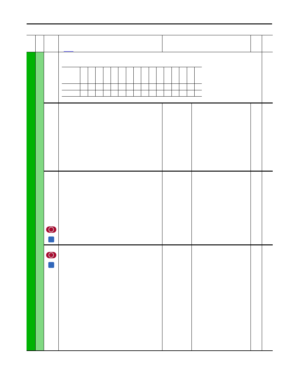
[Dig In Status]
Status of the digital inputs.
Read Only
565
566
567
568
569
570
571
572
573
574
575
576
[Dig In Term 1]
[Dig In Term 2]
[Dig In Term 3]
[Dig In Term 4]
[Dig In Term 5]
[Dig In Term 6]
[Dig In Term 7]
[Dig In Term 8]
[Dig In Term 9]
[Dig In Term 10]
[Dig In Term 11]
[Dig In Term 12]
Status of the digital inputs.
0 = Low
1 = High
Default:
Min/Max:
Read Only
0 / 1
16-bit
Int
1276
1277
1278
1279
1280
1281
1282
1283
1387
1388
1389
1390
[Inversion In 1]
[Inversion In 2]
[Inversion In 3]
[Inversion In 4]
[Inversion In 5]
[Inversion In 6]
[Inversion In 7]
[Inversion In 8]
[Inversion In 9]
[Inversion In 10]
[Inversion In 11]
[Inversion In 12]
inverts the digital input signal.
Default:
Options:
0
0 =
1 =
“Disabled”
“Disabled”
“Enabled”
16-bit
Int
1391
[ContactorControl]
Selects the type of contactor to be controlled by the drive. Either style of
contactor (AC or DC) can be used, with or without dynamic braking (DB)
contactor.
• “AC Cntctr” indicates an AC contactor is used. See note 1 below.
• “AC Cntctr+DB” indicates that an AC contactor and dynamic brake
resistor is used. See note 1 below.
• “DC Cntctr” indicates a DC contactor is used.
• “DC Cntctr+DB” indicates that a DC contactor and dynamic brake resistor
is used.
The type of control selected determines how many I/O points will be
required for contactor control and status.
• “AC Cntctr” or “DC Cntctr” = 1 (relay) digital output, 1 digital input is
used.
• “AC Cntctr+DB” or “DC Cntctr+DB” = 2 (relay) digital outputs, 1 digital
input is used.
Notes:
• 1. When 1 “AC Cntctr” or 2 “AC Cntctr+DB” is selected, there is a 400 ms
delay to power up before SCR firing can begin. The delay is needed to
determine correct input voltage phasing.
• 2. Option 1 was changed from “Contactor”, option 2 was changed from
“Contactor+DB”, and options 3 and 4 were added for firmware version
2.001.
Default:
Options:
1 =
0 =
1 =
2 =
3 =
4 =
“AC Cntctr”
“None”
“AC Cntctr”
“AC Cntctr+DB”
“DC Cntctr”
“DC Cntctr+DB”
16-bit
Int
Fil
e
Gr
oup
No
.
Parameter Name & Description
See
page 110
for symbol descriptions
Values
Da
ta
T
yp
e
Rela
ted
Options
Re
se
rv
ed
Re
se
rv
ed
Re
se
rv
ed
Re
se
rv
ed
D
igital
In12
D
igital
In11
D
igital
In10
Di
gi
ta
l I
n9
Di
gi
ta
l I
n8
Di
gi
ta
l I
n7
Di
gi
ta
l I
n6
Di
gi
ta
l I
n5
Di
gi
ta
l I
n4
Di
gi
ta
l I
n3
Di
gi
ta
l I
n2
Di
gi
ta
l I
n1
Default
x
x
x
x
0
0
0
0
0
0
0
0
0
0
0
0
Bit
15
14
13
12
11
10
9
8
7
6
5
4
3
2
1
0
A
A