Rockwell Automation 20P PowerFlex Digital DC Drive User Manual
Page 207
Rockwell Automation Publication 20P-UM001I-EN-P - February 2013
207
Troubleshooting
Chapter 4
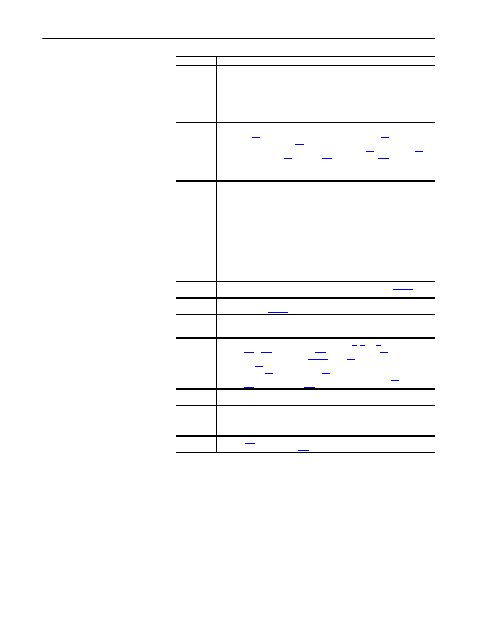
DigInCflctC
2
More than one physical input has been configured to the same input function. Multiple
configurations are not allowed for the following input functions.
Forward/Reverse
Run Reverse
Run Forward
Jog Forward
Jog Reverse
Speed Select 1
Speed Select 2
Speed Select 3
Acc2 / Dec2
Accel 2
Decel 2
Run
FB Cfg Cflct
2
One of the following has occurred:
• Par
[Fdbk Device Type] does not equal 3 “Armature” and Par
[Spd Loss Flt Cfg] is
set to “Alarm” while Par
[SpdReg FB Bypass] is set to “Disabled”.
• Par 414 [Fdbk Device Type] is set to 4 “Resolver” and Pars
[Resolver Pos Sel],
[Resolver Spd Sel],
[PID Source],
[Line Spd Source], or
[Ref Spd Source] are
selecting a resolver signal.
• Par 414 [Fdbk Device Type] is set to 1 “Encoder” and Pars 786, 1021, 1204, or 1284 are
selecting an encoder signal.
FldCfg Cflct
2
The selected operating mode of the field controller is in conflict with another setting in the
drive or a permanent magnet motor is incorrectly configured. This alarm displays under the
following conditions:
• Par
[Field Mode Sel] = “Field Weaken” or “External” and Par
[SpdReg FB Bypass]
= “Enabled”
• Par 469 [Field Mode Sel] = “Field Weaken” or “External” and Par
= “Armature”
• Par 469 [Field Mode Sel] = “Field Weaken” or “External” and Par
[Spd Loss Flt Cfg] =
“Alarm”
• Par 469 [Field Mode Sel] = “Field Weaken” or “Base Speed” and Par
[Field Reg En] =
“Disabled”
• Par 469 [Field Mode Sel] = “Base Speed” and Par
[Force Min Field] = “Enabled”
• Par 469 [Field Mode Sel] = “Base Speed” and Par
Min Fld”
Fld Current Loss
1
The field current is too low. See the “Fld Current Loss” fault description on
for more
information.
Motor Overload
1
The selected motor overload current level has been exceeded. See the “Motor Overload” fault
description on
for more information.
Motor Over Temp 1
The motor has exceeded its temperature rating (as signaled by the thermistor connected to
the drive terminals 78 and 79). See the “Motor Over Temp” fault description on
more information.
Ref Cflct
2
1. More than one of the drive's reference inputs (Pars
and
[Encoder Out Sel], or Par
[Resolver Spd Sel])
are set to the same value. See
on page
or Speed Reference Selection on
for a graphical representation of the drive's reference selections.
2. Both Pars
[Resolver Pos Sel] and
[Resolver Spd Sel] are non-zero.
3. More than one of the following parameters contains the same value:
[PID Source],
[Line Spd Source], and
[Ref Spd Source].
Spd Fdbk Err
1
With Par
[Spd Loss Flt Cfg] set to 1 “Alarm” an error condition associated with the
selected speed feedback device (analog tachometer, encoder, or resolver) was detected.
Spd Fdbk Loss
1
With Par
[Spd Loss Flt Cfg] set to 1 “Alarm”, the speed feedback device selected in Par
[Fdbk Device Type] is indicating less than 5% of Par
measured armature voltage is greater than the value of Par
“Spd Fdbk Loss” fault description on page
for more information.
Start At PowerUp 1
[Start At Powerup] is enabled. The drive may start at any time after drive power up
and the time specified in Par
[Powerup Delay] has elapsed.
Alarm
Type
Description