Rockwell Automation 20P PowerFlex Digital DC Drive User Manual
Page 126
126
Rockwell Automation Publication 20P-UM001I-EN-P - February 2013
Chapter 3
Programming and Parameters
MOT
O
R C
O
NTROL
Fie
ld Con
fig
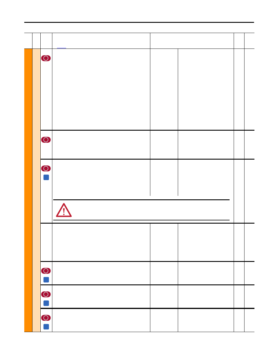
469
[Field Mode Sel]
Operating mode of the field controller.
• “Base Speed” = The motor field is regulated with constant current and
controls the motor from zero to base speed. If a curve is defined through
Pars 916, 917 and 918 [Fld Const xx Pct], this value will change linearly
through Par 467 [Max Fld Curr Pct] (which is a percentage of the nominal
flux value set in Par 280 [Nom Mtr Fld Amps]).
• “Field Weaken” = The motor field is regulated with a combination of
torque and constant power (armature and field regulation -- field
weakening). The maximum armature voltage is configured in Par 175
[Rated Motor Volt]. When using a DC contactor, this parameter is set to
this option, and Par 458 [SpdReg FB Bypass] is set to 1 “Enabled,” the
armature voltage feedback terminals A1 and A2 must be connected to the
motor terminals A1 and A2, respectively.
• “External” = The motor field power is supplied by an external rectifier/
converter (the drive’s field output is disabled).
• “PM External” = External field created by a permanent magnet (PM)
motor.
Note: Option 3 “PM External” was added for firmware version 5.002.
Default:
Options:
0 =
0 =
1 =
2 =
3 =
“Base Speed”
“Base Speed”
“Field Weaken”
“External”
“PM External”
16-bit
Int
456,
916,
917,
918,
921
497
[Field Reg Enable]
Enables/Disables the field regulator. Leave set to the default value for
permanent magnet motor applications.
• “Enabled” = The field regulator is enabled and controlling the field
output.
• “Disabled” = The field regulator is disabled (the field current is zero).
Default:
Options:
1 =
0 =
1 =
“Enabled”
“Disabled”
“Enabled”
16-bit
Int
498
[Force Min Field]
Enables/Disables the minimum field current value. Leave set to the default
value for permanent magnet motor applications.
• “Enabled” = The field current corresponds to the value set via Par 468
[Min Fld Curr Pct].
• “Disabled” = The field current is regulated based on the quadrant mode
and situation in which the drive is operating.
Note: This parameter can be assigned to a digital input (35 “Force MinFld”).
Default:
Options:
0 =
0 =
1 =
“Disabled”
“Disabled”
“Enabled”
16-bit
Int
499
[Field Economy En]
When this parameter is set to 1 = “Enabled” and the value in Par 107 [Speed
Zero Level] is reached (after the amount of time specified in Par 1407 [Field
Econ Delay] has elapsed), the minimum field current (set via Par 468 [Min Fld
Curr Pct]) is produced. Leave set to the default value for permanent magnet
motor applications.
• “Disabled” = Disables field economy
• “Enabled” = Enables field economy
Default:
Options:
1 =
0 =
1 =
“Enabled”
“Disabled”
“Enabled”
16-bit
Int
395,
468,
1407
916
[Fld Const 40 Pct]
Current value at 40% of the rated field flux. Leave set to the default value for
permanent magnet motor applications.
Default:
Min/Max:
Units:
40.00
0.00 / 100.00
%
Real
469
917
[Fld Const 70 Pct]
Current value at 70% of the rated field flux. Leave set to the default value for
permanent magnet motor applications.
Default:
Min/Max:
Units:
70.00
0.00 / 100.00
%
Real
469
918
[Fld Const 90 Pct]
Current value at 90% of the rated field flux. Leave set to the default value for
permanent magnet motor applications.
Default:
Min/Max:
Units:
90.00
0.00 / 100.00
%
Real
469
Fil
e
Gr
oup
No
.
Parameter Name & Description
See
page 110
for symbol descriptions
Values
Da
ta
T
yp
e
Rela
ted
A
ATTENTION: Enabling (forcing) the minimum field current while the drive is running could result in excessive motor
speed, equipment damage, and/or bodily injury.
A
A
A