Rockwell Automation 20P PowerFlex Digital DC Drive User Manual
Page 142
142
Rockwell Automation Publication 20P-UM001I-EN-P - February 2013
Chapter 3
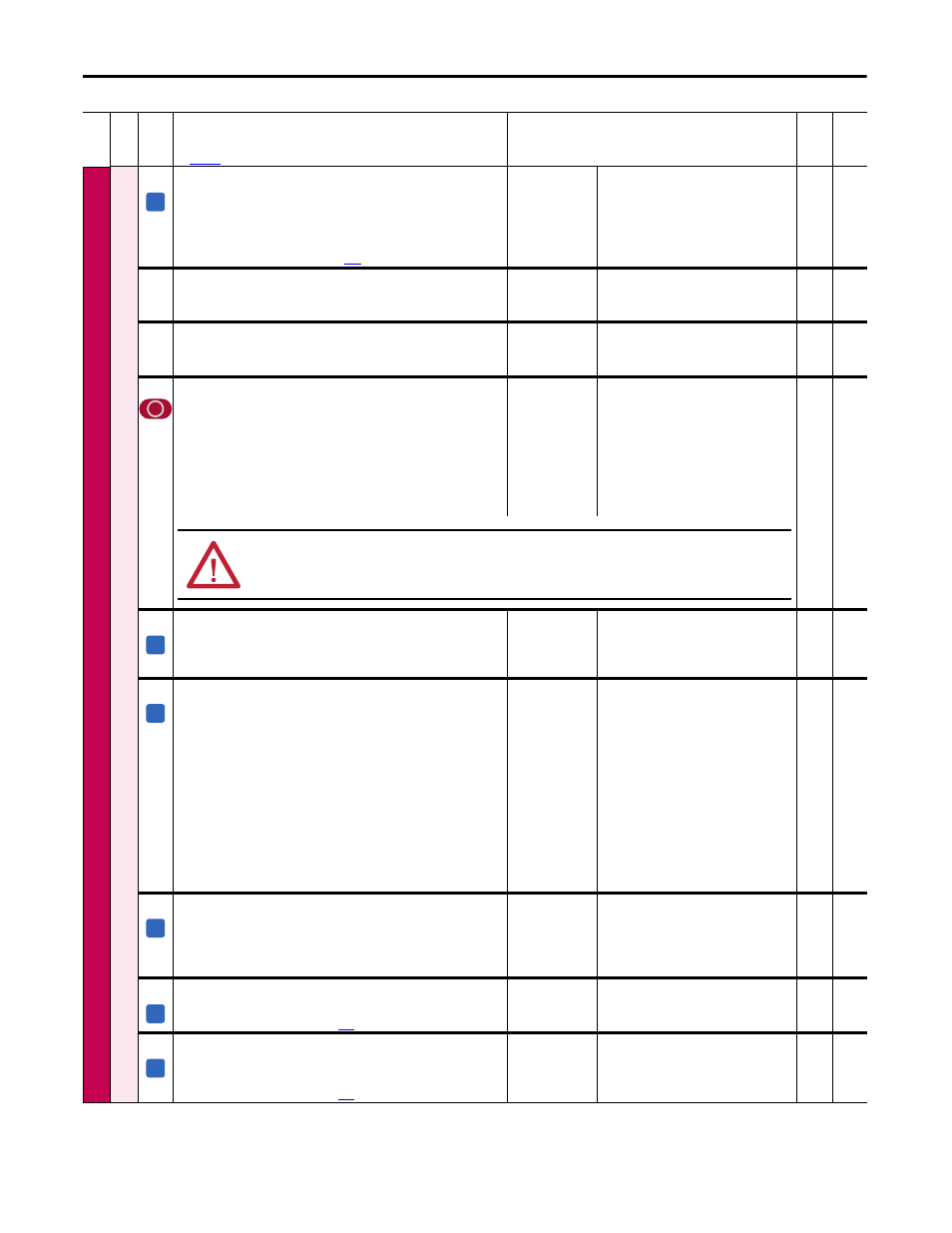
Programming and Parameters
SPEE
D C
O
MMAND
Speed Regul
at
or
126
[Spd Zero P Gain]
The proportional gain of the speed regulator that is only active when the
value of the speed reference and actual speed = 0. This parameter is only
active when Par 125 [Spd Zero P En] = 1 “Enabled”. Used in the Zero Speed
function.
Note: See Speed Zero Function on page
for more information.
Default:
Min/Max:
Units:
3.00
0.00 / 100.00
%
Real
238
[SpdOut FiltGain]
First order lead/lag filter gain on the speed regulator output signal.
Note: This parameter was added for firmware version 3.001.
Default:
Min/Max:
1.000
0.000 / 2.000
Real
239
239
[SpdOut FiltBW]
First order lead/lag filter bandwidth on the speed regulator output signal.
Note: This parameter was added for firmware version 3.001.
Default:
Min/Max:
Units:
0
0 / 2000
ms
16-bit
Int
238
242
[Speed Reg En]
Enables/Disables the speed regulator output to the torque/current regulator.
• “Enabled” = The speed regulator output is connected to the input of the
torque/current regulator.
• “Disabled” = The speed regulator output is not connected to the input of
the torque/current regulator. Par 39 [Torque Ref] is connected to the input
of the current regulator.
Note: This parameter is only available for use with firmware version 2.005
and lower.
Default:
Options:
1 =
0 =
1 =
“Enabled”
“Disabled”
“Enabled”
16-bit
Int
39,
41,
236
348
[Lock Speed Integ]
Enables or disables the integral (I) function of the speed regulator.
• “Not active” = The integral component of the speed regulator is enabled.
• “Active” = The integral component of the speed regulator is disabled.
Default:
Options:
1 =
0 =
1 =
“Not active”
“Active”
“Not active”
16-bit
Int
388
[Flying Start En]
Enables/Disables the ability of the drive to connect to a spinning motor at
actual rpm when a start command is issued.
• “On” = When the drive is turned on, the speed of the motor is measured
and the ramp output is set accordingly. The drive then runs at the set
reference value.
• “Off” = When the drive is turned on, the ramp starts from zero.
Main uses:
• To connect to a motor that is already spinning due to its load (for example,
in the case of a pump, the flowing medium).
• Re–connection to a spinning motor after a fault or alarm.
Note: If the Flying Start function is disabled (off), ensure that the motor is not
spinning when the drive is turned on, or harsh motor deceleration in current
limit may occur.
Default:
Options:
0 =
0 =
1 =
“Off”
“Off”
“On”
16-bit
Int
444
[Spd Reg P Filter]
Time constant used by the filter for the Speed Feedback circuit. Filtering of
the high frequency components of the speed feedback signal is useful in the
case of elastic coupling between the motor and load (i.e., joints or belts).
Note: This parameter was renamed for firmware version 4.001.
Default:
Min/Max:
Units:
0
0 / 1000
ms
16-bit
Int
121,
122
445
[Spd Up Gain Pct]
The Speed Up function gain as a percentage of Par 446 [Speed Up Base].
Note: See Speed Up Function on page
for more information.
Default:
Min/Max:
Units:
0.00
0.00 / 100.00
%
Real
446
446
[Speed Up Base]
The Speed Up function maximum gain. This value corresponds to 100% of Par
445 [Spd Up Gain Pct].
Note: See Speed Up Function on page
for more information.
Default:
Min/Max:
Units:
1000.00
0.00 / 16000.00
ms
Real
445
Fil
e
Gr
oup
No
.
Parameter Name & Description
See
page 110
for symbol descriptions
Values
Da
ta
T
yp
e
Rela
ted
A
ATTENTION: Failure to correctly set speed and voltage parameters or provide overspeed protection when operating as a
torque/current regulator could result in high motor speeds, equipment damage, and/or personal injury.
A
A
A
A
A