Rockwell Automation 20P PowerFlex Digital DC Drive User Manual
Page 172
172
Rockwell Automation Publication 20P-UM001I-EN-P - February 2013
Chapter 3
Programming and Parameters
UTILIT
Y
Al
arms
585
[Overspeed Val]
Speed value (rpm) at which an “Overspeed” fault (F25) will occur.
Notes: Typically set at 110% of Par 162 [Max Feedback Spd]. See Chapter 4 for a list
of fault and alarm descriptions. This parameter was added for firmware version
3.001.
Default:
Min/Max:
Units:
1925
0 / 7800
rpm
16-bit
Int
162
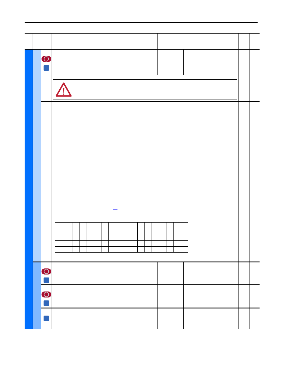
1380 [Drive Alarm 1]
Alarm conditions that currently exist in the drive. For each bit, 1 = Condition true, and 0 = Condition false.
Bit 0
“DigInCflctA” - Digital input functions are in conflict.
Bit 1
“DigInCflctB” - A digital Start input has been configured without a Stop input or other functions are in conflict.
Bit 2
“DigInCflctC” - More than one physical input has been configured for the same input function.
Bit 3
“BipolarCflct” - Parameter 1322 [Direction Mode] is set to “Bipolar” or “Reverse Dis” and one or more of the following digital input
functions is configured: “Fwd/Reverse,” “Run Forward,” “Run Reverse,” “Jog Forward” or “Jog Reverse.”
Bit 4
“Ref Cflct” - Multiple speed or position references are configured.
Bit 5
“CntactrCflct” - Contactor input functions are in conflict.
Bit 6
“FB Cfg Cflct” - A speed feedback configuration error has occurred or is being provided by multiple sources.
Bit 7
“Overvoltage” - There is an overvoltage on the armature circuit.
Bit 8
“Over Temp” - The motor has exceeded its temperature rating [as signaled by the thermistor (PTC) or thermal switch connected to the drive
terminals 78 and 79].
Bit 9
“Aux Input” - An auxiliary input interlock is open or a voltage (15…30 V) or reference signal is missing for the digital input set to 14 “Aux
Fault” (only updates if Par 354 [Aux Inp Flt Cfg] is set to 1 “Alarm”).
Bit 10 “Field Loss” - The field current is too low.
Bit 11 “SpdFdbk Loss” - The drive is not receiving a speed feedback signal.
Bit 12 “PwrUp Start” - Indicates that the drive is starting or has automatically resumed running at commanded speed after drive input power was
restored.
Bit 13 “Mtr Overload” - Indicates when the Motor Overload alarm level has been reached.
Bit 14 “FldCfg Cflct” - Indicates a field configuration conflict.
Bit 15 “Spd Fdbk Err” - Indicates an encoder or resolver error.
Notes: See Chapter 4 -Troubleshooting on page
for information. The name of bit 11 was changed from “Encoder Loss” and bits 13 and 14 were
added for firmware version 3.001. The name of bit 4 “AnalogCflct”, bit 6 “Encoder Cflct”, and bit 11 “Feedback Loss” were changed and bit 15 was
added for firmware version 5.002.
16-bit
Int
1322
Us
er
D
ef
in
ed
50
[UsrDsplyMult0]
Numerator in the calculation for user-defined, drive speed display units.
Note: This parameter is not used.
Default:
Min/Max:
1
1 / 1073741823
32-bit
Int
51
[UsrDsplyDiv0]
Denominator in the calculation for user-defined, drive speed display units.
Note: This parameter is not used.
Default:
Min/Max:
1
1 / 1073741823
32-bit
Int
53
[UsrValMult1]
Numerator in the calculation for scaling the user-defined, drive speed display
units.
Note: This parameter is not used.
Default:
Min/Max:
1
1 / 32767
16-bit
Int
Fil
e
Gr
oup
No
.
Parameter Name & Description
See
page 110
for symbol descriptions
Values
Da
ta
T
yp
e
Rela
ted
A
ATTENTION: Verify that you have correctly set this parameter appropriately for your application. Incorrectly setting this
parameter may cause a hazard of personal injury and/or equipment damage.
Options
Spd F
db
k
Er
r
Fl
dC
fg
C
flc
t
Mt
r O
ve
rloa
d
PwrUp Star
t
SpdF
dbk L
oss
Fi
el
d L
os
s
Au
x In
put
Ov
er
T
em
p
Ov
er
vo
ltag
e
FB
Cfg
Cflc
t
Cntac
trCflc
t
Ref Cflc
t
BipolarCflc
t
DigI
nCflc
tC
DigI
nCflc
tB
DigI
nCflc
tA
Default
0
0
0
0
0
0
0
0
0
0
0
0
0
0
0
0
Bit
15
14
13
12
11
10
9
8
7
6
5
4
3
2
1
0
A
A
A