Figure 21, Po w er fl ex d c drive – Rockwell Automation 20P PowerFlex Digital DC Drive User Manual
Page 49
Rockwell Automation Publication 20P-UM001I-EN-P - February 2013
49
Installation and Wiring
Chapter 1
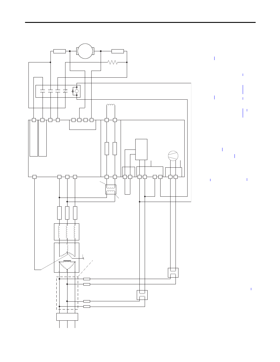
Figure 21 - Power Wiring with DC Output/Dynamic Braking Contactor and a Dynamic Brake
C
D
Po
w
er
Fl
ex
D
C
Drive
36
(8)
34
(4)
(on I/O TB4)
19
(5)
(+2
4V - on I/O TB2)
Co
nt
ro
l
Bo
ar
d P/
S
115V
or
230V
(1)
U2
V2
F2
35
(8)
U
V
W
3 P
has
e
AC lin
e
L1
L2
L3
U1
V1
C1
D1
F1
FS1
(3)
FS1
(3)
FU1
FV1
FU
FU
Field Power Terminal Block
Control Power / Relay Ouputs
Terminal Block
A1
A2
Armature Volt.
Fdbk. Term.
1A1
1A2
U3
V3
Fan Power Terminal Block
(9)
230V
FU
FU
Line Reactor
(2)
Lockable
Installation
Disconnect
SB
(1)
SA
(1)
Aux
(N
.O
. R
ela
y)
M1 DC
Cn
tc
tr
13
14
L1
L2
L3
A1
T1
T2
T3
A2
M
A1
A2
FS2
(6)
FS2
(6)
DB
Re
s.
(7)
FS1
(3)
These connections
must be taken from
the primary side of
the Isolation Transformer
or Line Reactor
(clean power).
AC Input
Voltage
AC Input
Voltage
Isolation
Transformer
(2)
Safety Ground
PE
AC Input
Voltage
460 VAC
Max. or
230 VAC
Min.
(10)
(1)
For
fram
e B
an
d C
d
riv
es
onl
y,
a ju
mpe
r is
req
ui
red
bet
w
ee
n
terminals SA a
nd
SB for 11
5V
AC
contro
l input po
wer. Se
e Co
r o
n
pa
ge
for more inf
ormatio
n.
(2
) An
Is
ol
at
io
n Tra
nsf
or
mer a
nd/
or
3
…
5%
im
pe
da
nce
Line
Re
act
or
is req
ui
red.
If
the
Iso
la
tio
n Tr
an
sf
or
me
r p
rov
id
es
th
e r
equ
ired
3…
5% im
ped
anc
e,
a L
ine
Re
actor
is no
t requ
ired
. See
on
pa
ge
and
o
n p
age
fo
r
re
commend
ations.
(3)
AC
in
pu
t fuses f
or
th
e a
rm
ature
con
verter a
re cu
sto
m
er sup
pl
ied
fo
r f
rame
A
and
B
dri
ves
a
nd
are
int
erna
lly
mo
unt
ed
on
fr
am
e
C a
nd
D
dri
ves.
See
n p
ag
fo
r f
use recommen
datio
ns.
(4
) Pa
r 1
40
[D
ig
ital
In8
Se
l] se
t to
3
1
“Co
nt
act
or
”
(5
) If
us
ing
th
e
+2
4V
in
te
rn
al
po
w
er s
up
ply
, t
erm
ina
l 1
8 (
24
V
com
m
on
) m
us
t be
ju
mp
ered
to
te
rmi
nal
3
5 (d
ig
ital
inp
ut
co
mm
on)
.
(6)
Custom
er sup
pli
ed
arma
tu
re o
utpu
t fu
se
s
are re
qui
red
on
fo
ur
qua
dra
nt
and
are
reco
mme
nde
d o
n t
w
o qu
ad
ra
nt
Fra
m
e A
a
nd
B d
rive
s.
See
ge
fo
r fuse rec
omm
endations.
(7
) The
“E
nab
le”
in
pu
t mus
t be
remo
ve
d i
n ord
er
to pe
rfo
rm
a
dy
na
m
ic
b
ra
ki
ng st
op.
(8)
P
ar
13
91 [C
ontactorC
ontr
ol] =
3 “D
C Cntct
r” an
d
Pa
r 13
92 [R
elay Out 1 Sel]
= 24 “Co
ntact
orDB
”.
Import
ant:
Terminal 35 an
d 36 are on the
Co
ntro
l P
ower / Relay Out
puts Termi
nal
bl
ock
, NOT the
I/O termin
al b
lo
cks.
See
Fi
gu
re
35
on pa
ge
63
…
on
pa
ge
.
(9
) Frame
C
& D
d
rive
s
on
ly re
qui
re a
n ex
ternal
po
w
er s
up
pl
y f
or
th
e hea
tsi
nk c
oolin
g fan
. Se
e F
o
n pa
ge
a
nd
s o
n p
age
for more inf
ormatio
n.
(10)
See F
n p
age
.